
Table of Contents
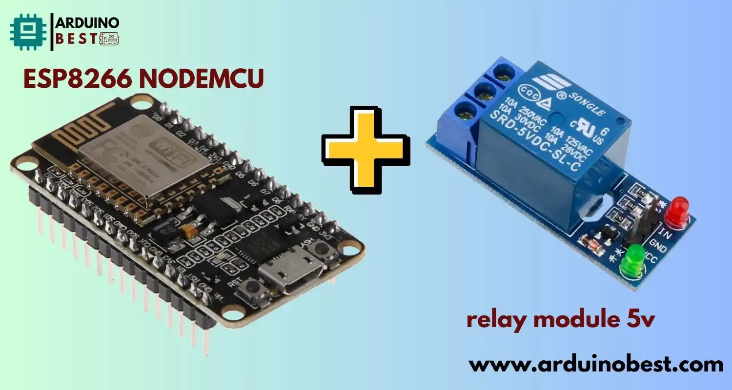
Controlling high-voltage appliances with a microcontroller is a fundamental part of many home automation and IoT projects. One of the most popular and affordable combinations is using the ESP8266 NodeMCU with relay module 5v. This setup lets you switch devices on or off remotely over Wi-Fi, opening the door to countless automation possibilities.
In this guide, you’ll learn everything from wiring and coding to safety considerations and advanced use cases.
Understanding the Components
ESP8266 NodeMCU: Features and Specifications
- Microcontroller with built-in Wi-Fi
- Operates on 3.3V logic
- USB programmable via Arduino IDE
- Compact and cost-effective
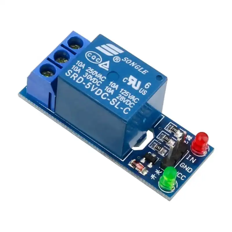
5V Relay Module: Functionality and Types
- Works like a switch controlled electronically
- Can control AC devices like fans, bulbs, or heaters
- Available in 1-channel to 8-channel modules
Compatibility Considerations
- ESP8266 uses 3.3V logic, while relay modules often require 5V
- Use a transistor or level shifter for safe interfacing
- Always isolate high voltage using optocouplers where possible
For a hands-on example, check out this ESP8266 Relay Module AC Web Server tutorial by Random Nerd Tutorials.
Safety Precautions When Working with Relays and AC Mains
- Never touch the relay’s high-voltage side while powered
- Ensure isolation with optocouplers or use mechanical separation
- Use plastic enclosures and avoid exposed terminals
- Disconnect power before making any circuit changes
Wiring the ESP8266 NodeMCU with a 5V Relay Module
Required Components
- ESP8266 NodeMCU board
- 5V relay module (single or multi-channel)
- Jumper wires
- Breadboard
- Power supply (external 5V recommended)
Circuit Diagram and Connections
- IN pin of relay to GPIO (e.g., D1 on NodeMCU)
- VCC of relay to 5V (external or USB powered)
- GND to common ground
Powering the Relay Module
- Use an external 5V supply if using multiple relays
- Avoid drawing too much current from the NodeMCU board
- Consider isolating the power ground for protection
Here’s a great walkthrough on interfacing a relay module with NodeMCU to get started quickly.
Programming the ESP8266 NodeMCU to Control the Relay
Setting Up the Arduino IDE
- Install the ESP8266 board package in Arduino IDE
- Select NodeMCU 1.0 from the board manager
Writing the Control Code
#define RELAY_PIN D1

void setup() {
  pinMode(RELAY_PIN, OUTPUT);
}

void loop() {
  digitalWrite(RELAY_PIN, HIGH); // Turn relay ON
  delay(1000);
  digitalWrite(RELAY_PIN, LOW); // Turn relay OFF
  delay(1000);
}
Uploading and Testing
- Connect NodeMCU via USB
- Upload the sketch
- Use Serial Monitor for debugging
Integrating with Home Automation Systems
Using Blynk for Remote Control
- Create a Blynk project and note Auth Token
- Install the Blynk library
- Connect to Wi-Fi and control the relay via smartphone
Voice Control with Google Assistant or Alexa
- Integrate via IFTTT or Home Assistant
- Use ESPHome firmware for Alexa compatibility
Scheduling and Automation
- Implement timers in code
- Use Node-RED or MQTT to trigger relays based on events
Check out this ESP8266 home automation project to explore further.
Troubleshooting Common Issues
- Relay Not Switching: Check voltage levels, ensure proper GPIO pin
- ESP8266 Resetting: Confirm current draw is within limits
- Wi-Fi Connectivity Issues: Add reconnection code and check signal strength
Advanced Applications and Projects
- Multi-relay Control: Use shift registers or I/O expanders
- Energy Monitoring: Combine with ACS712 current sensor
- Security Automation: Use PIR sensors to trigger relays
Frequently Asked Questions (FAQs)
Can I use a 5V relay module directly with 3.3V GPIO?
Some modules work, but it’s safer to use a transistor or logic shifter.
How do I power both ESP8266 and the relay in standalone mode?
Use a common 5V power source with regulators for NodeMCU.
What GPIOs are safe for relays?
D1, D2, and D5–D8 are commonly used; avoid GPIO0, GPIO2, and GPIO15 during boot.
How to control relay over internet?
Use platforms like Blynk, MQTT, or build a web server.
Why is my relay behaving erratically?
Check for insufficient power or signal interference.
Conclusion
Integrating a 5V relay module with ESP8266 NodeMCU opens up a world of possibilities in IoT and home automation. Whether you’re looking to control household appliances, automate lighting, or build a DIY smart security system, this combination provides a low-cost, flexible, and wireless solution.
By understanding how the ESP8266 NodeMCU communicates with the relay module, and how to properly wire and program it, you can confidently design and build smart systems that are both efficient and scalable. From basic relay switching to more advanced applications like scheduling, voice commands, and energy monitoring, the potential is limited only by your creativity.
Safety should always be a top priority when working with high-voltage components. Be sure to isolate your circuits, use proper power supplies, and avoid exposing any live terminals. Even simple precautions can go a long way in ensuring your project runs smoothly and safely.
As you continue exploring the world of smart devices, this foundational setup will serve as a reliable starting point. With ESP8266 NodeMCU and a 5V relay module, you’re not just switching relays — you’re powering innovation. So go ahead, experiment, and bring your automation ideas to life.
Projects ESP8266 nodemcu :
1- ESP8266 NodeMCU: A Comprehensive Guide to IoT Development
2- Control LED with ESP8266 NodeMCU: A Beginner’s Guide
3- Integrating a Joystick with ESP8266 NodeMCU: A Comprehensive Guide
4- esp8266 nodemcu with Flame Sensor
5- ESP8266 NodeMCU with Heartbeat Sensor