
Table of Contents
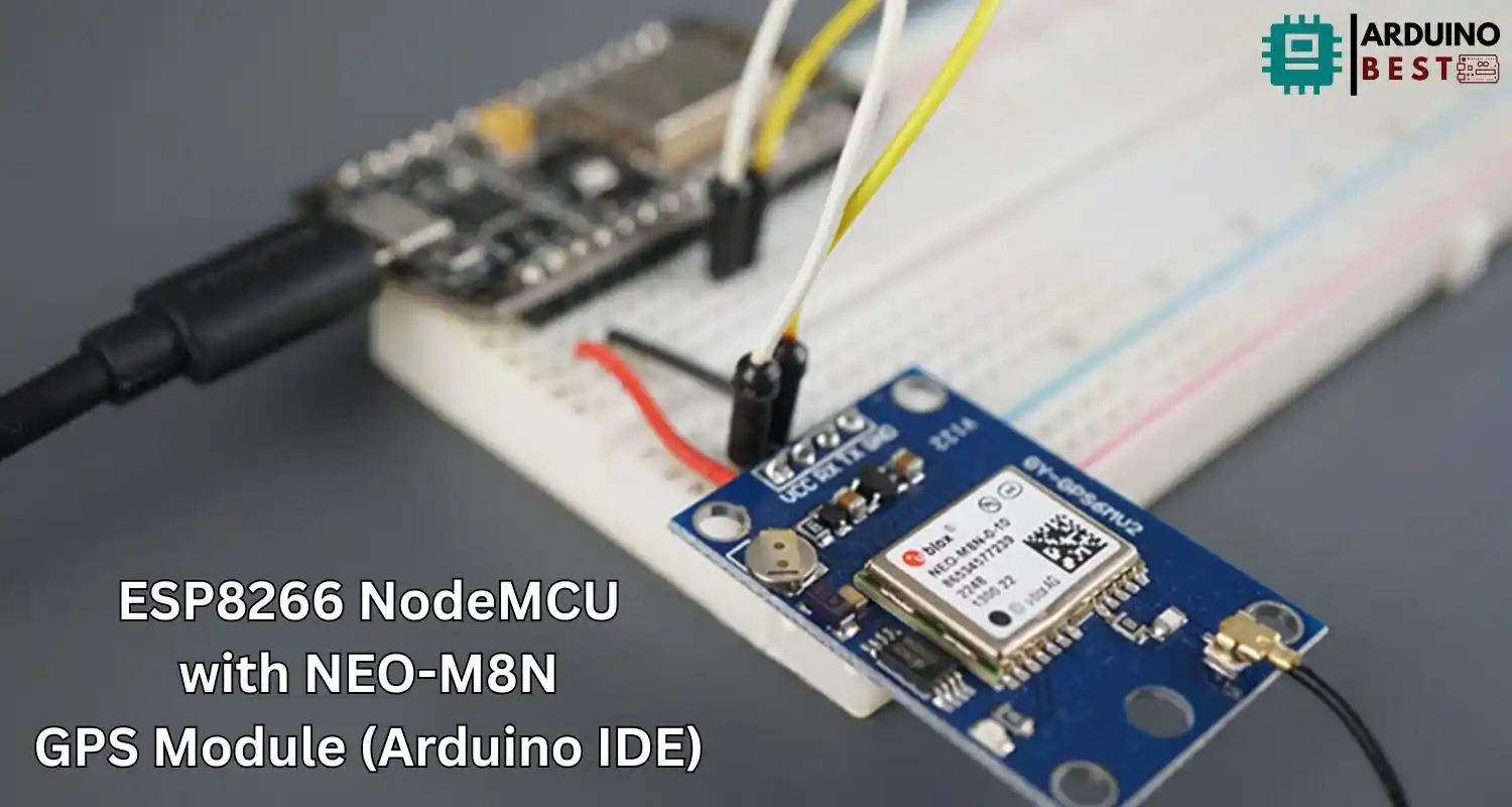
The combination of the ESP8266 NodeMCU and the NEO-M8N GPS module offers a powerful and compact solution for real-time location tracking in IoT and embedded applications. By leveraging the simplicity of the Arduino IDE, developers can easily set up and deploy GPS-enabled systems with minimal coding effort.
In this comprehensive guide, you’ll learn how to connect the NEO-M8N GPS module with an ESP8266 NodeMCU, configure the Arduino IDE, parse GPS data, and explore practical use cases—all while optimizing your code for reliable GPS performance and minimal power consumption.
If you’re new to this setup, check out this step-by-step tutorial for installing ESP8266 in Arduino IDE. You’ll need it to ensure your development environment is properly configured before connecting your GPS module.
Understanding the NEO-M8N GPS Module
The NEO-M8N from u-blox is a high-performance GPS module that supports multiple GNSS systems including GPS, GLONASS, Galileo, and BeiDou. It is highly accurate and features:
- Concurrent reception of up to three GNSS systems
- Fast time-to-first-fix
- Up to 10Hz update rate
- Built-in EEPROM and Qwiic/I2C support
Compared to older modules like the NEO-6M, the NEO-M8N offers improved accuracy, faster acquisition, and better overall satellite coverage.
For more details on how this module works in practice, take a look at this hands-on GPS project using ESP8266 and NEO-M8N.
Overview of ESP8266 NodeMCU
The ESP8266 NodeMCU is a popular Wi-Fi-enabled microcontroller that is widely used in IoT development due to its:
- Built-in USB interface for easy programming
- Integrated Wi-Fi module
- Low cost and wide community support
- Compatibility with Arduino IDE and Lua
Its flexibility and wireless capabilities make it a perfect companion for mobile GPS applications.
Required Components and Tools
To build a GPS tracking system, you’ll need the following:
- ESP8266 NodeMCU board
- NEO-M8N GPS module
- Jumper wires
- Breadboard
- Arduino IDE installed
- TinyGPSPlus library
Wiring the NEO-M8N GPS Module to ESP8266
The NEO-M8N uses UART communication, so connect its TX and RX pins to the ESP8266 using a SoftwareSerial port:
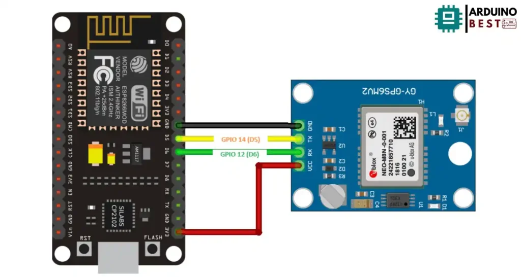
- NEO-M8N TX → ESP8266 D7 (GPIO13)
- NEO-M8N RX → ESP8266 D6 (GPIO12)
- VCC → 3.3V (Important: DO NOT use 5V)
- GND → GND
Use a logic level shifter if your GPS module is not 3.3V tolerant.
Setting Up Arduino IDE for ESP8266
Follow these steps to prepare the Arduino IDE:
- Open Preferences and paste the ESP8266 board URL
- Go to Boards Manager and install esp8266 by ESP8266 Community
- Install the TinyGPSPlus library from the Library Manager
This configuration allows seamless communication between the NodeMCU and the GPS module using the Arduino IDE.
Writing and Uploading the Arduino Sketch
Here’s a basic code snippet using the TinyGPSPlus library:
#include <SoftwareSerial.h>
#include <TinyGPS++.h>

// Define the RX and TX pins for Software Serial
#define RX 14
#define TX 12

#define GPS_BAUD 9600

// The TinyGPS++ object
TinyGPSPlus gps;

// Create an instance of Software Serial
SoftwareSerial gpsSerial(RX, TX);

void setup() {
  // Serial Monitor
  Serial.begin(115200);

  // Start Serial 2 with the defined RX and TX pins and a baud rate of 9600
  gpsSerial.begin(GPS_BAUD);
  Serial.println("Software Serial started at 9600 baud rate");
}

void loop() {
  // This sketch displays information every time a new sentence is correctly encoded.
  unsigned long start = millis();

  while (millis() - start < 1000) {
    while (gpsSerial.available() > 0) {
      gps.encode(gpsSerial.read());
    }
    if (gps.location.isUpdated()) {
      Serial.print("LAT: ");
      Serial.println(gps.location.lat(), 6);
      Serial.print("LONG: ");
      Serial.println(gps.location.lng(), 6);
      Serial.print("SPEED (km/h) = ");
      Serial.println(gps.speed.kmph());
      Serial.print("ALT (min)= ");
      Serial.println(gps.altitude.meters());
      Serial.print("HDOP = ");
      Serial.println(gps.hdop.value() / 100.0);
      Serial.print("Satellites = ");
      Serial.println(gps.satellites.value());
      Serial.print("Time in UTC: ");
      Serial.println(String(gps.date.year()) + "/" + String(gps.date.month()) + "/" + String(gps.date.day()) + "," + String(gps.time.hour()) + ":" + String(gps.time.minute()) + ":" + String(gps.time.second()));
      Serial.println("");
    }
  }
}
Upload this sketch using the proper board and port selection in the IDE.
Parsing and Displaying GPS Data
The TinyGPSPlus library efficiently parses data from the NEO-M8N and provides:
- Latitude and longitude with up to 6 decimal places
- Altitude
- Speed and heading
- Date and time in UTC
Monitor output via the Serial Monitor and ensure that the GPS has a clear view of the sky for reliable satellite fix.
Enhancing the Project
Add more features to your project with these ideas:
- Display GPS data on an OLED screen using the Adafruit_SSD1306 library
- Log coordinates to an SD card module for offline tracking
- Send GPS data to an HTTP server using ESP8266’s Wi-Fi functionality
For an example, this Instructables guide shows how to display GPS coordinates on an OLED.
Troubleshooting Common Issues
If the GPS module isn’t working correctly, consider:
- Checking if the module has a clear line of sight to the sky
- Verifying voltage levels (the NEO-M8N is 3.3V)
- Reversing the TX/RX connections if data isn’t being received
- Confirming the baud rate (default is usually 9600)
Real-World Applications
You can apply this GPS setup in:
- DIY vehicle tracking systems
- Personal GPS loggers
- Geofencing and boundary detection
- Wildlife monitoring and environmental sensing
FAQs
How do I connect the NEO-M8N to ESP8266?
Use SoftwareSerial to connect TX and RX. Match the GPS module’s TX to ESP8266’s RX, and vice versa.
Which library is best for GPS data in Arduino?
The TinyGPSPlus library is widely used for its simplicity and functionality with GPS NMEA data.
Why is my GPS not locking onto satellites?
Make sure the module is outdoors with a clear view of the sky. GPS signal reception is limited indoors.
Can I use this setup indoors?
Not reliably. GPS modules like the NEO-M8N are designed for outdoor use and may not work well indoors.
How do I show GPS data on an OLED display?
Use libraries like Adafruit_GFX and Adafruit_SSD1306 to print the parsed GPS data on a 128×64 OLED screen.
Conclusion
Combining the ESP8266 NodeMCU with the NEO-M8N GPS module using the Arduino IDE provides a cost-effective, powerful, and highly flexible solution for developing smart GPS-based systems. This integration allows developers to build projects capable of precise geolocation, real-time data transmission, and IoT connectivity with minimal hardware and coding complexity.
Thanks to libraries like TinyGPSPlus, parsing GPS data becomes straightforward, enabling access to accurate location, altitude, speed, and time information. Whether you’re building a mobile GPS logger, a vehicle tracking system, or a cloud-connected geofencing application, this setup offers the foundational tools to get started quickly and scale with more features.
Optional enhancements, such as integrating an OLED display, adding data logging via SD cards, or sending GPS coordinates to a web server, allow for greater customization and real-world usability. By leveraging the versatility of the ESP8266 NodeMCU and the reliability of the NEO-M8N GPS, you can develop applications that are both efficient and practical for a wide range of tracking and navigation needs.
Projects ESP8266 nodemcu
1- ESP8266 NodeMCU: A Comprehensive Guide to IoT Development
2- Control LED with ESP8266 NodeMCU: A Beginner’s Guide
3- Integrating a Joystick with ESP8266 NodeMCU: A Comprehensive Guide
4- esp8266 nodemcu with Flame Sensor
5- ESP8266 NodeMCU with Heartbeat Sensor
6- ESP8266 NodeMCU with KY-027 Magic Cup Light
7- ESP8266 NodeMCU with Hall Magnetic Sensor
8- ESP8266 NodeMCU with relay module 5v
9- ESP8266 NodeMCU with Linear Hall Sensor