
Table of Contents
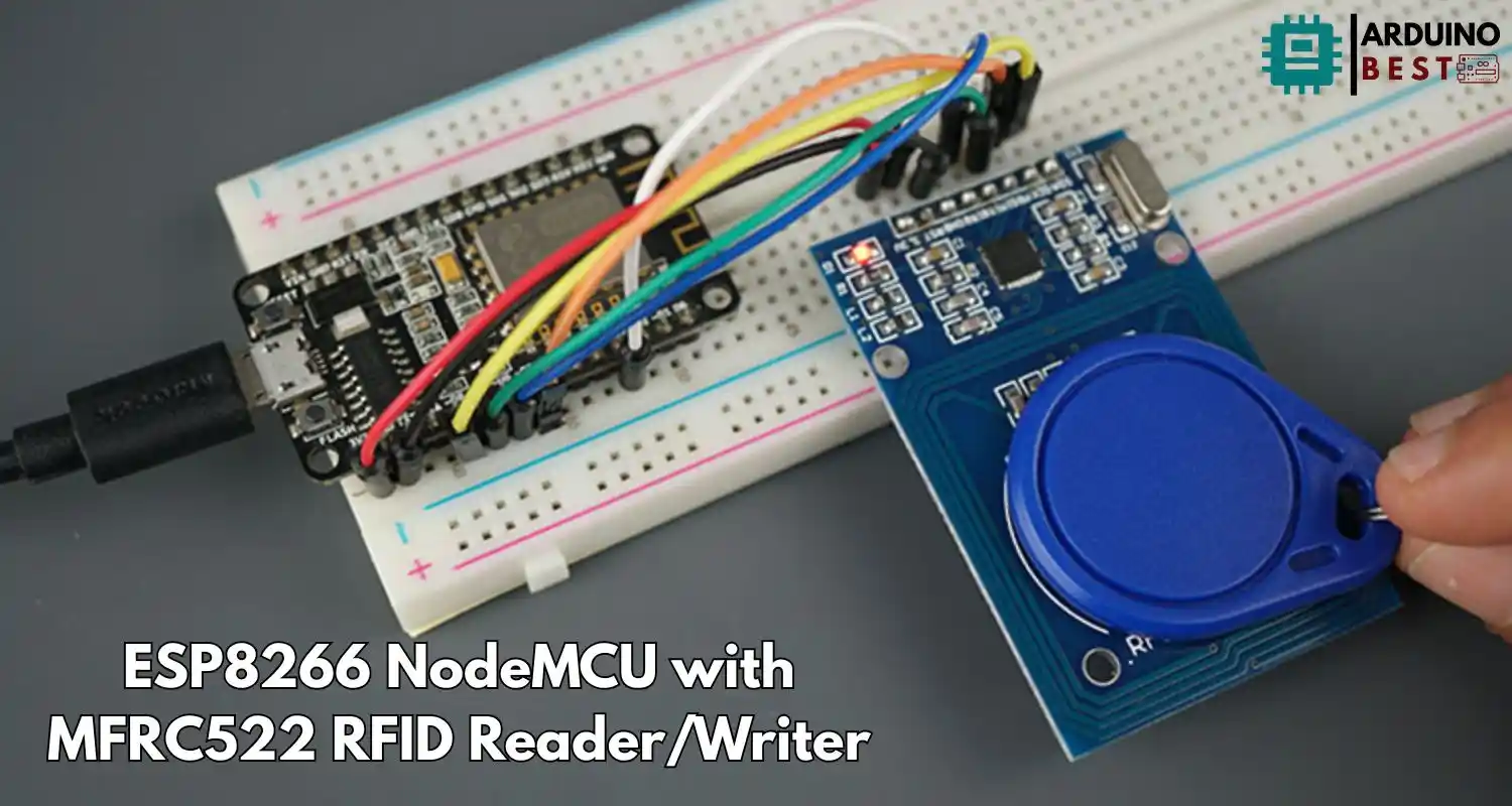
The combination of ESP8266 NodeMCU with MFRC522 RFID Reader/Writer creates a powerful foundation for building smart IoT applications such as access control systems, attendance logging, and inventory tracking. With its low cost, wireless capabilities, and robust RFID support, this setup is ideal for both beginners and advanced developers.
In this guide, you’ll learn how to connect, configure, and code your ESP8266 NodeMCU with the MFRC522 RFID Reader, along with best practices and practical project ideas. Whether you’re building a smart door lock or tracking employee IDs, this tutorial covers everything you need to get started.
To begin, you’ll need to install the Arduino IDE and prepare your development environment. For more advanced use cases or technical support, the ESP8266 Community Forum is a valuable resource.
Understanding the Components
ESP8266 NodeMCU
The ESP8266 NodeMCU is a low-cost Wi-Fi-enabled microcontroller with great features:
- 80 MHz CPU clock speed
- Wi-Fi support for IoT applications
- Multiple GPIO pins
- SPI, I2C, and UART communication protocols
MFRC522 RFID Reader/Writer
The MFRC522 is a 13.56 MHz RFID reader that supports MIFARE tags. It’s compact, affordable, and commonly used with Arduino-compatible boards.
Key features:
- Communicates via SPI
- Supports MIFARE 1K and 4K cards
- Operating range: 2–5 cm
- Read and write support
Required Materials and Tools
To get started, gather the following:
- ESP8266 NodeMCU board
- MFRC522 RFID Reader/Writer module
- Jumper wires
- Breadboard
- RFID cards or key fobs
- Micro USB cable
- Computer with Arduino IDE installed
Software requirements:
- Arduino IDE
- MFRC522 library
- ESP8266 board definitions for Arduino IDE
Wiring the MFRC522 to ESP8266 NodeMCU
Here’s how to wire the MFRC522 to the ESP8266 using SPI:
| MFRC522 Pin | ESP8266 Pin |
|---|---|
| SDA | D2 (GPIO4) |
| SCK | D5 (GPIO14) |
| MOSI | D7 (GPIO13) |
| MISO | D6 (GPIO12) |
| IRQ | Not used |
| GND | GND |
| RST | D1 (GPIO5) |
| 3.3V | 3.3V |
Ensure all connections are secure. The MFRC522 should only be powered with 3.3V—5V may damage the module.
Setting Up the Development Environment
- Install the latest Arduino IDE.
- Add ESP8266 support: go to Preferences > Additional Board URLs and paste:
http://arduino.esp8266.com/stable/package_esp8266com_index.json - Install MFRC522 library via Library Manager (search for “MFRC522”).
Once set up, select the appropriate board (NodeMCU 1.0) and port under the Tools menu.
Programming the ESP8266 for RFID Operations
Reading RFID Tags
Here’s a simple sketch to read the UID from an RFID card:
#include <MFRC522v2.h>
#include <MFRC522DriverSPI.h>
//#include <MFRC522DriverI2C.h>
#include <MFRC522DriverPinSimple.h>
#include <MFRC522Debug.h>

// Learn more about using SPI/I2C or check the pin assigment for your board: https://github.com/OSSLibraries/Arduino_MFRC522v2#pin-layout
MFRC522DriverPinSimple ss_pin(15);

MFRC522DriverSPI driver{ss_pin}; // Create SPI driver
//MFRC522DriverI2C driver{};     // Create I2C driver
MFRC522 mfrc522{driver};         // Create MFRC522 instance

MFRC522::MIFARE_Key key;

byte blockAddress = 2;
byte newBlockData[17] = {"Rui Santos - RNT"};
//byte newBlockData[16] = {0,0,0,0,0,0,0,0,0,0,0,0,0,0,0,0};   // CLEAR DATA
byte bufferblocksize = 18;
byte blockDataRead[18];

void setup() {
  Serial.begin(115200);  // Initialize serial communication
  while (!Serial);       // Do nothing if no serial port is opened (added for Arduinos based on ATMEGA32U4).

  mfrc522.PCD_Init();    // Init MFRC522 board.
  Serial.println(F("Warning: this example overwrites a block in your card, use with care!"));

  // Prepare key - all keys are set to FFFFFFFFFFFF at chip delivery from the factory.
  for (byte i = 0; i < 6; i++) {
    key.keyByte[i] = 0xFF;
  }
}

void loop() {
  // Check if a new card is present
  if (!mfrc522.PICC_IsNewCardPresent() || !mfrc522.PICC_ReadCardSerial()) {
    delay(500);
    return;
  }

  // Display card UID
  Serial.print("----------------\nCard UID: ");
  MFRC522Debug::PrintUID(Serial, (mfrc522.uid));
  Serial.println();

  // Authenticate the specified block using KEY_A = 0x60
  if (mfrc522.PCD_Authenticate(0x60, blockAddress, &key, &(mfrc522.uid)) != 0) {
    Serial.println("Authentication failed.");
    return;
  }

  // Write data to the specified block
  if (mfrc522.MIFARE_Write(blockAddress, newBlockData, 16) != 0) {
    Serial.println("Write failed.");
  } else {
    Serial.print("Data written successfully in block: ");
    Serial.println(blockAddress);
  }

  // Authenticate the specified block using KEY_A = 0x60
  if (mfrc522.PCD_Authenticate(0x60, blockAddress, &key, &(mfrc522.uid)) != 0) {
    Serial.println("Authentication failed.");
    return;
  }

  // Read data from the specified block
  if (mfrc522.MIFARE_Read(blockAddress, blockDataRead, &bufferblocksize) != 0) {
    Serial.println("Read failed.");
  } else {
    Serial.println("Read successfully!");
    Serial.print("Data in block ");
    Serial.print(blockAddress);
    Serial.print(": ");
    for (byte i = 0; i < 16; i++) {
      Serial.print((char)blockDataRead[i]);  // Print as character
    }
    Serial.println();
  }

  // Halt communication with the card
  mfrc522.PICC_HaltA();
  mfrc522.PCD_StopCrypto1();

  delay(2000);  // Delay for readability
}
Upload the code and open the Serial Monitor. You’ll see the UID when a tag is scanned.
Writing Data to RFID Tags
You can also write to blocks on the tag using the MIFARE_Write() function. Note that most tags require authentication using default keys (0xFF…).
Steps:
- Authenticate block
- Use
MIFARE_Write()to write 16-byte data - Confirm the write with
MIFARE_Read()
Important: Avoid writing to sector trailer blocks unless you’re experienced with RFID security settings.
Practical Applications and Projects
Projects using this setup include:
- RFID Door Lock: Control a relay to unlock a door when authorized tags are scanned.
- Attendance Logger: Log entries with UID and timestamp to an SD card or send to a server.
- Inventory Tracker: Scan products in/out of storage and sync with an online database.
- Home Automation Access: Use RFID tags to trigger lights, alarms, or devices.
You can explore more examples at Random Nerd Tutorials.
Troubleshooting Common Issues
If your project isn’t working:
- Check wiring: SPI misconfiguration is the most common issue.
- Voltage mismatch: Make sure you’re using 3.3V, not 5V.
- Library issues: Confirm you’re using the correct MFRC522 library.
- UID not showing: Ensure the RFID card is placed close to the reader and the Serial Monitor baud rate matches.
FAQs
How do I connect MFRC522 to ESP8266?
Use SPI pins. Connect SDA to D2, SCK to D5, MOSI to D7, MISO to D6, RST to D1, GND to GND, and VCC to 3.3V.
Can I use multiple RFID readers with one ESP8266?
Yes, but it requires multiplexing SPI communication or using separate select lines.
What is the range of MFRC522?
Typically around 2–5 cm depending on the tag and power supply.
How to secure data on RFID tags?
Set password keys and use the authentication process built into the MFRC522 chip.
Is it possible to clone RFID tags with this setup?
Technically yes, but it’s ethically questionable. Use only for authorized projects.
Conclusion
The ESP8266 NodeMCU combined with the MFRC522 RFID Reader/Writer offers an efficient, low-cost platform for building a variety of RFID-based IoT applications. From simple authentication systems to full-fledged access control or inventory solutions, this setup allows developers to bring contactless technology to life with ease.
By integrating RFID functionality with Wi-Fi capabilities, you unlock the potential to connect and control your devices remotely—making your projects smarter, scalable, and more responsive. Whether you’re a hobbyist experimenting at home or a developer prototyping a commercial application, this combination delivers flexibility and performance.
Throughout this guide, you’ve learned how to connect the hardware, configure your development environment, and write code to read and write RFID tags. With a solid understanding of both the components and their capabilities, you’re now ready to innovate beyond the basics. Explore cloud integration, build a database-connected access system, or expand your network with multiple readers. The possibilities are limited only by your creativity.
Projects ESP8266 nodemcu
1- ESP8266 NodeMCU: A Comprehensive Guide to IoT Development
2- Control LED with ESP8266 NodeMCU: A Beginner’s Guide
3- Integrating a Joystick with ESP8266 NodeMCU: A Comprehensive Guide
4- esp8266 nodemcu with Flame Sensor
5- ESP8266 NodeMCU with Heartbeat Sensor
6- ESP8266 NodeMCU with KY-027 Magic Cup Light
7- ESP8266 NodeMCU with Hall Magnetic Sensor
8- ESP8266 NodeMCU with relay module 5v
9- ESP8266 NodeMCU with Linear Hall Sensor