Table of Contents
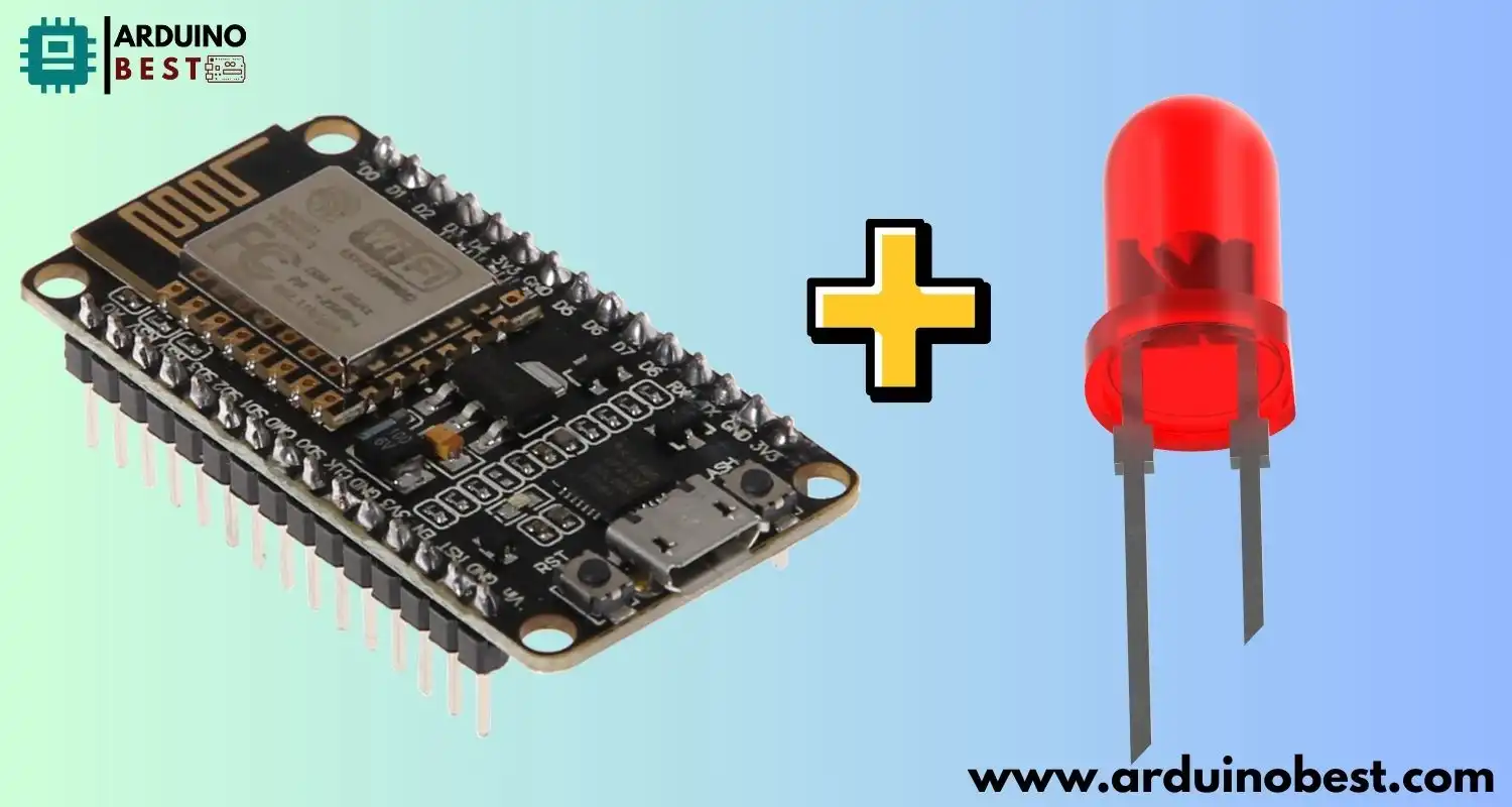
The esp8266 nodemcu with led is a low-cost, highly versatile development board that is widely used in Internet of Things (IoT) projects. With built-in Wi-Fi capabilities, it offers a flexible platform for creating networked devices. One common application for this module is controlling LEDs, which can serve as indicators or provide feedback in various systems. In this article, we’ll explore how to control LEDs with the ESP8266 NodeMCU, from the basic blinking program to advanced control via web interfaces.
Understanding ESP8266 NodeMCU
The ESP8266 NodeMCU is powered by a microcontroller that features a Wi-Fi chip, making it a popular choice for IoT applications. It has GPIO (General Purpose Input/Output) pins, which can be used to interface with various external components like LEDs.
- Technical Specifications:
- Microcontroller: ESP8266 with 80 MHz clock speed
- Flash Memory: 4MB
- GPIO Pins: 11 general-purpose pins
- Onboard LED: Can be used for basic testing without external components
The first step in using this board is setting up the Arduino IDE for ESP8266 development. Follow the steps provided in this Instructables tutorial to ensure your environment is correctly configured for easy programming.
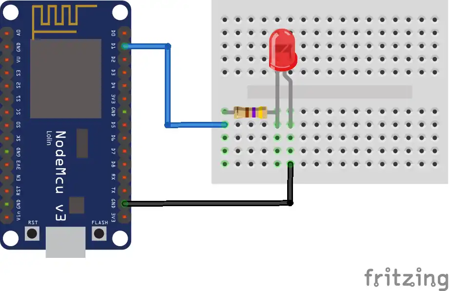
Circuit

The Basic LED Blink Program
Once you have the ESP8266 NodeMCU set up in the Arduino IDE, you can begin writing code to control the LEDs. The simplest program to start with is the blink program, which toggles the onboard LED at regular intervals.
- Blinking the Onboard LED:
- The onboard LED on the NodeMCU is connected to GPIO pin 2.By writing a simple Arduino sketch, you can blink the onboard LED on and off every second.
void setup() {
  pinMode(LED_BUILTIN, OUTPUT); // Initialize the LED pin as an output
}

void loop() {
  digitalWrite(LED_BUILTIN, LOW); // Turn the LED on (active low)
  delay(1000); // Wait for a second
  digitalWrite(LED_BUILTIN, HIGH); // Turn the LED off
  delay(1000); // Wait for a second
}
- Blinking an External LED:
- To control an external LED, connect the long leg (anode) of the LED to a GPIO pin and the short leg (cathode) to ground through a current-limiting resistor (typically 220Ω).
- You can modify the previous code to control this external LED by changing the pin number.
Advanced LED Control Techniques
Once you’ve got the basic blink program working, it’s time to explore more advanced techniques for controlling your LED. The ESP8266 NodeMCU offers more than just simple on/off control—it supports advanced features such as PWM (Pulse Width Modulation) and web-based control.
PWM for LED Brightness Control
PWM allows you to control the brightness of an LED by rapidly turning it on and off at varying duty cycles. The longer the LED stays on compared to the off period, the brighter it appears.
- The ESP8266 can generate PWM signals on specific pins. This can be used to dim or brighten LEDs smoothly.
Here’s a basic code example for controlling the brightness of an LED with PWM:
cppCopyEditint ledPin = 5; // GPIO pin connected to LED
int brightness = 0; // Initial brightness level
int fadeAmount = 5; // Change in brightness each time

void setup() {
  pinMode(ledPin, OUTPUT);
}

void loop() {
  analogWrite(ledPin, brightness); // Set LED brightness
  brightness += fadeAmount;

  // Reverse the direction of the fading at the ends of the brightness range
  if (brightness <= 0 || brightness >= 255) {
    fadeAmount = -fadeAmount;
  }

  delay(30);
}
This code fades the LED in and out, giving you a smooth brightness control.
Creating a Web Server to Control LED
One powerful feature of the ESP8266 NodeMCU is its ability to host a web server. With this, you can control your LED remotely using a web browser.
- Set up a web server that listens for incoming HTTP requests to toggle the state of the LED. You can control the LED through a simple interface, such as a button or slider, on the webpage.
- The HTML and Arduino code required to build such a server can be found in this tutorial from Random Nerd Tutorials.
Here’s an example of how you can set up a basic server:
cppCopyEdit#include <ESP8266WiFi.h>
WiFiServer server(80); // Create a server on port 80

void setup() {
  Serial.begin(115200);
  WiFi.begin("yourSSID", "yourPassword");

  while (WiFi.status() != WL_CONNECTED) {
    delay(1000);
    Serial.println("Connecting to WiFi...");
  }

  server.begin(); // Start the web server
  pinMode(LED_BUILTIN, OUTPUT);
}

void loop() {
  WiFiClient client = server.available();

  if (client) {
    String request = client.readStringUntil('\r');
    client.flush();

    if (request.indexOf("/LED=ON") != -1) {
      digitalWrite(LED_BUILTIN, LOW); // LED on
    }
    if (request.indexOf("/LED=OFF") != -1) {
      digitalWrite(LED_BUILTIN, HIGH); // LED off
    }

    // Return the web page
    client.print("HTTP/1.1 200 OK\r\nContent-Type: text/html\r\n\r\n");
    client.print("<html><body><h1>Control LED</h1>");
    client.print("<a href=\"/LED=ON\"><button>Turn ON</button></a>");
    client.print("<a href=\"/LED=OFF\"><button>Turn OFF</button></a>");
    client.print("</body></html>");

    delay(1);
    client.stop();
  }
}
Integrating a Slider for LED Brightness Adjustment
To make your project even more interactive, you can add a slider to control the LED’s brightness through your web interface. This can be achieved using AJAX to send data to the server without refreshing the page.
Learn how to implement the PWM slider for brightness control with this detailed guide from Random Nerd Tutorials.
Troubleshooting Common Issues
Working with the ESP8266 NodeMCU may sometimes present challenges. Here are a few common issues and how to troubleshoot them:
- Connectivity Problems:
- Ensure that your Wi-Fi credentials are correct and that the ESP8266 is within range of your router.
- If you’re using a static IP, make sure there are no conflicts with other devices on your network.
- LED Not Responding:
- Check the GPIO pin configuration and make sure you have the correct pin mode set in the code.
- Verify that the external LED is properly connected and that you’re using a current-limiting resistor.
Security Considerations
When controlling LEDs through a web interface, security is a key concern, especially if you plan to make your system accessible over the internet.
- Securing the Web Interface: Implement basic authentication and use HTTPS to ensure secure communication.
- Protecting GPIO Pins: Use resistors and external transistors to protect the GPIO pins from high current.
Practical Applications
The ESP8266 NodeMCU with LED control has numerous applications in home automation, status indicators, and user feedback systems. Some practical use cases include:
- Home Automation: Automate your LED lighting to turn on/off or adjust brightness based on time or motion sensors.
- Status Indicators: Use LEDs to indicate the status of various systems, such as whether a device is online or offline.
- User Feedback: Provide real-time feedback to users, such as using a blinking LED to indicate progress in a task.
FAQs
How do I connect multiple LEDs to ESP8266?
You can use GPIO expanders or multiplexers to control multiple LEDs with the ESP8266. Each GPIO pin can handle a single LED, so expanders help manage larger arrays.
Can I use ESP8266 to control RGB LEDs?
Yes, you can control RGB LEDs by using PWM to adjust the intensity of each color channel. A common cathode or common anode RGB LED can be connected to the ESP8266 for colorful lighting effects.
What is the maximum current ESP8266 GPIO pins can handle?
Each GPIO pin on the ESP8266 can handle up to 12mA safely. If you need to drive higher-current LEDs, consider using a transistor or mosfet to act as a switch.
How can I make the LED control accessible over the internet?
To make your LED control accessible online, use port forwarding on your router or implement Dynamic DNS services. This will allow you to access the web server hosted on your ESP8266 from anywhere.
Is it possible to control the LED using voice commands?
Yes, you can integrate your ESP8266 NodeMCU with Alexa or Google Assistant to control LEDs via voice commands. This requires setting up an IFTTT applet or using platforms like Blynk.
Conclusion
In conclusion, the ESP8266 NodeMCU offers endless possibilities for controlling LEDs, making it a perfect choice for both beginners and advanced users in the world of IoT. Whether you’re starting with a basic LED blink program or diving into more complex tasks such as PWM brightness control and building a web-based interface, this versatile board makes it easy to bring your ideas to life. The built-in Wi-Fi capability allows you to control LEDs remotely, while the integration with the Arduino IDE ensures a smooth and intuitive development process.
The ability to control LEDs with the ESP8266 NodeMCU is not only useful for simple applications but also paves the way for more advanced home automation, status indicator, and user feedback systems. By experimenting with different setups, you can develop innovative IoT projects that suit your needs and creativity.
The potential of the ESP8266 NodeMCU is immense. It provides an accessible entry point for those looking to explore the world of electronics and wireless communication. So, grab your NodeMCU board, start experimenting with LED control, and let your imagination drive the next big idea in the IoT world!
Arduino Projects:
1- Complete Guide for DHT11/DHT22 Humidity and Temperature Sensor With Arduino
2- DHT11 – Temperature and Humidity Sensor
3- DHT22 – Temperature and Humidity Sensor (more accurate than DHT11)
4- BMP180 – Barometric Pressure and Altitude Sensor
5- BMP280 – Barometric Pressure & Temperature Sensor
6- BME280 – Temperature, Humidity, and Pressure Sensor
7- Arduino Flex Sensor Controlled Robot Hand
8- Arduino ECG Heart Rate Monitor AD8232 Demo
9- Arduino NRF24L01 Wireless Joystick Robot Car
10- Arduino Force Sensor Anti-Theft Alarm System
11- Arduino NRF24L01 Transceiver Controlled Relay Light
12- Arduino Rotary Encoder Controlled LEDs: A Complete Guide

