
Table of Contents
Introduction
The ESP8266 NodeMCU is a popular microcontroller for Internet of Things (IoT) projects, thanks to its built-in Wi-Fi capability and affordable price. Paired with a versatile component like the KY-029 Dual Color LED Module, you can create visually interactive projects with ease. This combination offers a simple yet effective way to control a bi-color LED, such as a red-green LED, with the flexibility of remote control and automation.
By understanding how to wire and program the ESP8266 NodeMCU with the KY-029 Dual Color LED Module, you’ll be able to develop creative IoT applications. If you’re looking to get started with controlling LEDs and other components through your Wi-Fi-enabled projects, consider checking out resources like Instructables – Quick Start to NodeMCU ESP8266 on Arduino IDE, which offer comprehensive tutorials.
What is the ESP8266 NodeMCU?
The ESP8266 NodeMCU is a Wi-Fi microcontroller, well-regarded for its small size, low cost, and powerful features. It operates at 3.3V and supports various programming platforms, including the popular Arduino IDE. Some key features include:
- Built-in Wi-Fi capabilities for remote communication
- 16 GPIO pins for interfacing with sensors and other components
- Support for PWM (Pulse Width Modulation), which is useful for controlling LED brightness
The NodeMCU board can be programmed using the Arduino IDE or other compatible platforms, making it ideal for beginners and experts alike. To help you get started, you can follow this DIYI0T – LED Tutorial for Arduino, ESP8266, and ESP32 guide.
Understanding the KY-029 Dual Color LED Module
The KY-029 Dual Color LED Module features a bi-color LED, meaning it has two separate LED elements inside: one red and one green. By controlling the two LEDs separately, you can create various color combinations (typically red, green, or yellow). The module is designed with a common cathode configuration, which simplifies wiring when working with microcontrollers like the ESP8266.
Key features of the KY-029 Dual Color LED Module include:
- Red and Green LED housed in one module
- Easy integration with microcontrollers like the ESP8266 using a few simple connections
- Ideal for status indication applications
You can find detailed instructions on how to integrate the KY-029 module in various projects from resources like SensorKit – KY-029 2-Color 3mm LED, which provides step-by-step wiring and coding examples.
Components Needed for the Project
To complete the project of controlling the KY-029 Dual Color LED Module with the ESP8266 NodeMCU, you’ll need the following components:
- ESP8266 NodeMCU board
- KY-029 Dual Color LED Module
- Breadboard and jumper wires
- Resistors (330Ω) for current limiting
- Power supply (5V)
Optional:
- External power supply if you’re working on a larger setup or need additional power.
Wiring Diagram and Circuit Setup
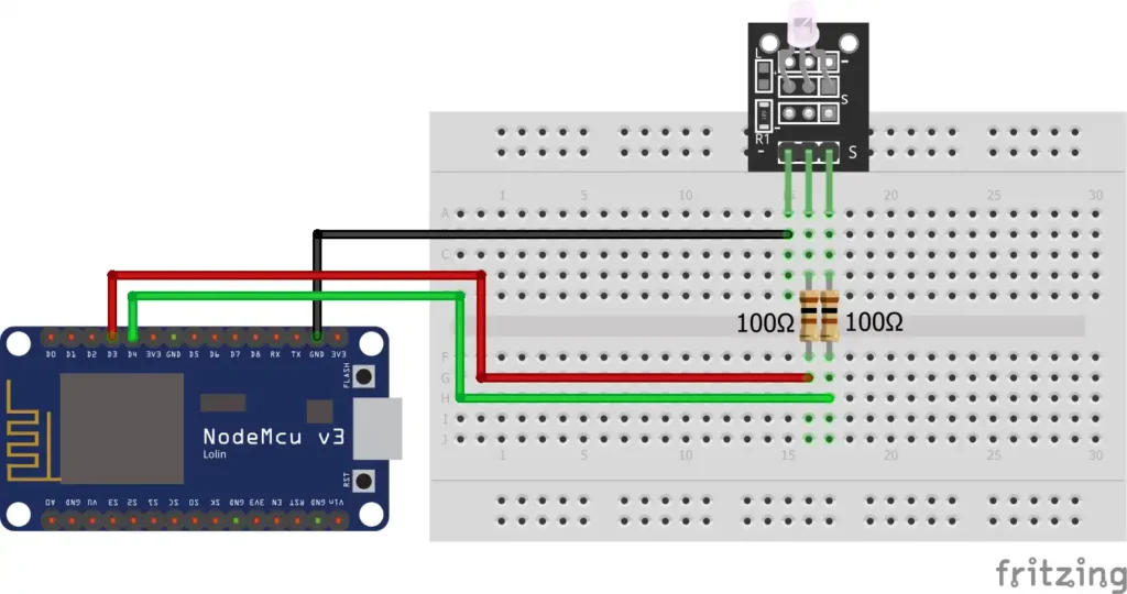
Setting up the circuit for the KY-029 Dual Color LED Module with the ESP8266 is straightforward. Follow these steps:
- Connect the common cathode (GND) pin of the KY-029 to the GND pin of the ESP8266 NodeMCU.
- Connect the red LED pin to a GPIO pin on the NodeMCU, for example, GPIO5 (D1).
- Connect the green LED pin to another GPIO pin, such as GPIO4 (D2).
- Use 330Ω resistors in series to limit the current to the LEDs.
You can check out circuit diagrams and further guidance in tutorials like Cirkit Designer – ESP8266 NodeMCU Controlled Dual LED Circuit for detailed visual instructions.
Programming the ESP8266 NodeMCU
Before programming, make sure your Arduino IDE is set up to work with the ESP8266 NodeMCU. Here’s a quick guide on how to do this:
- Install the ESP8266 board in the Arduino IDE via the Board Manager.
- Install necessary libraries such as
ESP8266WiFito enable Wi-Fi communication. - Write the code to control the KY-029 Dual Color LED Module by using digitalWrite or PWM commands.
Here is a simple code snippet to control the LEDs:
cppCopyEditint redPin = D1;  // GPIO5
int greenPin = D2;  // GPIO4

void setup() {
  pinMode(redPin, OUTPUT);
  pinMode(greenPin, OUTPUT);
}

void loop() {
  digitalWrite(redPin, HIGH);  // Turn on red LED
  digitalWrite(greenPin, LOW);  // Turn off green LED
  delay(1000);

  digitalWrite(redPin, LOW);  // Turn off red LED
  digitalWrite(greenPin, HIGH);  // Turn on green LED
  delay(1000);
}
You can learn more about setting up the Arduino IDE for ESP8266 from Random Nerd Tutorials – ESP8266 Web Server, which includes comprehensive examples for creating web-controlled LED systems.
Testing the Circuit
Once the wiring and code are in place, power on your setup. You should see the red LED turn on for one second, then switch to the green LED for another second. If the LEDs are not responding as expected, check your wiring connections and ensure that the correct GPIO pins are being used.
Advanced Applications and Use Cases
With the KY-029 Dual Color LED Module, you can build more advanced applications beyond simple LED blinking. Some potential uses include:
- Status indicators: Use the dual color LED to signal different system states, such as red for error and green for success.
- Traffic light simulation: Simulate a traffic light system with the red, yellow, and green colors.
- IoT integrations: Control the LEDs remotely through a web interface, allowing you to change colors based on real-time data.
FAQs
What is the maximum current rating for the KY-029 LED module?
The KY-029 module typically draws 20-30mA of current per LED, but it’s best to check the datasheet for specific limits.
Can I use a different resistor value for current limiting?
Yes, you can adjust the resistor value, but ensure the current does not exceed the LED’s rated maximum.
How do I control the brightness of the LED?
You can use PWM on the ESP8266 pins to adjust the brightness of the LED.
Is it possible to use the KY-029 module with other microcontrollers?
Yes, the KY-029 can be used with any microcontroller that supports digital output, such as the Arduino.
What are the limitations of using a common cathode LED module?
The main limitation is that it requires careful pin management because all the LEDs share a common ground.
Conclusion
Integrating the ESP8266 NodeMCU with the KY-029 Dual Color LED Module provides a simple yet powerful starting point for various IoT projects. This combination offers both beginners and experts the flexibility to create visually interactive and responsive systems with minimal hardware requirements. By leveraging the Arduino IDE, you can easily control the LED’s colors, such as red and green, and explore more advanced functionality, including remote control or status indication.
With the ability to manage multiple GPIO pins, utilize PWM for brightness control, and integrate into larger IoT networks, the ESP8266 NodeMCU opens up a world of possibilities for innovative applications. Whether you’re working on smart home systems, robotics, or data visualization, this project provides a solid foundation for more complex setups.
As you dive deeper into the capabilities of the ESP8266 and KY-029, experimenting with different configurations and extending your system’s functionality will help you unlock even more exciting IoT projects. The world of IoT is vast, and with the right tools and components, you can continue to innovate and build smart solutions tailored to your needs.
Projects ESP8266 nodemcu :
1- ESP8266 NodeMCU: A Comprehensive Guide to IoT Development
2- Control LED with ESP8266 NodeMCU: A Beginner’s Guide
3- Integrating a Joystick with ESP8266 NodeMCU: A Comprehensive Guide
4- esp8266 nodemcu with Flame Sensor
5- ESP8266 NodeMCU with Heartbeat Sensor
6- ESP8266 NodeMCU with KY-027 Magic Cup Light
7- ESP8266 NodeMCU with Hall Magnetic Sensor
8- ESP8266 NodeMCU with relay module 5v
9- ESP8266 NodeMCU with Linear Hall Sensor