
Table of Contents
Looking to build a fun and interactive electronics project using ESP8266 NodeMCU with 7 Color Flash ? In this guide, we’ll show you how to use the 7-color flash LED module (often KY-034) with the ESP8266 NodeMCU microcontroller. Whether you’re a beginner or an experienced maker, this project is perfect for exploring LED control, web interfaces, and IoT basics.
Introduction
The ESP8266 NodeMCU is a popular Wi-Fi-enabled microcontroller known for its ease of use, low cost, and versatility. Paired with a 7-color flashing LED module, it becomes a simple yet eye-catching project that demonstrates core principles of GPIO control, timing, and microcontroller programming.
In this tutorial, you’ll learn:
- How the KY-034 7-color LED module works.
- How to wire it to your ESP8266 NodeMCU.
- How to write code that controls the color flashes.
- How to extend this project with a simple web interface for remote control.
To get started, it helps to know more about the KY-034 7-Color Flash LED Module, including how it cycles through colors and how to interface it with microcontrollers like the NodeMCU.
You’ll also want to get familiar with the NodeMCU’s GPIO layout. Here’s a great ESP8266 pinout reference that explains which pins to use safely for I/O.
Understanding the Components
ESP8266 NodeMCU
The ESP8266 NodeMCU is a development board based on the ESP8266 Wi-Fi chip. It provides:
- USB-to-serial interface
- Onboard voltage regulator
- GPIO access
- Built-in Wi-Fi
Key features:
- 80/160 MHz CPU speed
- 4MB Flash memory
- Support for Lua and Arduino IDE
7-Color Flashing LED Module (KY-034)
This module uses a multicolor LED that flashes in a preset sequence. Unlike RGB LEDs, you can’t program individual colors—it flashes through them automatically once powered.
Module features:
- Voltage: 3.3V – 5V
- Color sequence: Red, Green, Blue, Yellow, Cyan, Purple, White
- Single digital input pin (on/off control)
Required Materials and Tools
Before starting, gather the following:
Hardware
- 1x ESP8266 NodeMCU board
- 1x KY-034 7-color LED module
- Jumper wires
- Breadboard
- USB cable (for programming)
Software
- Arduino IDE
- ESP8266 board manager installed
- Optional: Web browser for UI control
Circuit Design and Connections
Wiring Diagram
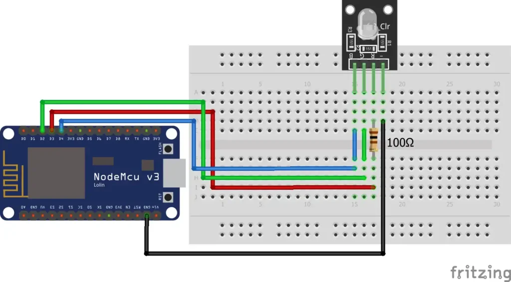
Here’s how to wire the LED module to your NodeMCU:
- KY-034
Signal→ NodeMCUD2(GPIO4) - KY-034
GND→ NodeMCUGND - KY-034
VCC→ NodeMCU3.3V
Power Considerations
- Ensure you’re powering from the 3.3V pin, not 5V, to protect the ESP8266.
- If using multiple LEDs, consider external power.
Common mistakes to avoid:
- Connecting to incorrect GPIO pins.
- Forgetting a shared ground.
- Using a digital-only module expecting PWM (this module doesn’t need PWM).
Programming the ESP8266 NodeMCU
Setting Up Arduino IDE
- Install the latest Arduino IDE
- In Preferences, add this URL to
Additional Board Manager URLs: bashCopyEdithttp://arduino.esp8266.com/stable/package_esp8266com_index.json - Go to Boards Manager, search for ESP8266, and install it.
Sample Code to Control KY-034
cppCopyEdit#define LED_PIN D2

void setup() {
  pinMode(LED_PIN, OUTPUT);
}

void loop() {
  digitalWrite(LED_PIN, HIGH); // Turn on LED
  delay(1000);                 // Wait 1 sec
  digitalWrite(LED_PIN, LOW);  // Turn off LED
  delay(1000);                 // Wait 1 sec
}
This simple code toggles power to the LED, causing it to start and stop its automatic color cycle.
Upload and Test
- Connect the NodeMCU via USB.
- Select correct board and port from Tools menu.
- Upload code and open Serial Monitor.
- You should see the LED flashing in various colors.
Enhancing the Project
Want to add some interaction? Let’s create a web-controlled LED using NodeMCU’s Wi-Fi.
Adding a Web Server
With a basic HTML page, you can toggle the LED from your browser:
cppCopyEdit#include <ESP8266WiFi.h>
#include <ESP8266WebServer.h>

const char* ssid = "Your_SSID";
const char* password = "Your_PASSWORD";

ESP8266WebServer server(80);

void handleRoot() {
  server.send(200, "text/html", "<h1>LED Controller</h1><a href='/on'>Turn On</a> | <a href='/off'>Turn Off</a>");
}

void setup() {
  pinMode(LED_PIN, OUTPUT);
  WiFi.begin(ssid, password);
  while (WiFi.status() != WL_CONNECTED) {
    delay(1000);
  }

  server.on("/", handleRoot);
  server.on("/on", [](){ digitalWrite(LED_PIN, HIGH); server.send(200, "text/html", "LED ON"); });
  server.on("/off", [](){ digitalWrite(LED_PIN, LOW); server.send(200, "text/html", "LED OFF"); });
  server.begin();
}

void loop() {
  server.handleClient();
}
Now you can control the 7-color flash LED from your phone or PC!
Expanding Further
- Add more LEDs on separate GPIOs.
- Control LEDs using MQTT for home automation.
- Sync with a sound sensor or motion detector.
Common Issues and Troubleshooting
Problem: LED doesn’t light up
Fix: Check wiring and pin definitions; ensure the module is powered from 3.3V.
Problem: Colors not cycling
Fix: This module auto-cycles when powered—if it’s not, your digital signal may be too low or too short.
Problem: ESP8266 keeps resetting
Fix: Likely a power issue—use a stable 3.3V supply and avoid drawing too much from the USB port.
FAQs
How do I power the 7-color LED module with ESP8266 NodeMCU?
You can safely power it from the 3.3V pin of the NodeMCU. Avoid 5V to prevent damaging the board.
Can I control the color sequence of the KY-034 module?
No, the module uses a self-flashing RGB LED with an internal IC that cycles through colors automatically. You can only toggle it on/off.
What are the GPIO limitations on ESP8266?
Not all GPIOs are safe for I/O. GPIO0, GPIO2, and GPIO15 have special functions during boot. Always refer to a pinout reference.
How can I expand this project to control more LEDs?
Use additional GPIOs or shift registers (like 74HC595) to control more outputs. You can also manage them via a web interface or a mobile app.
Is it possible to integrate this setup with smart home systems?
Yes! Using platforms like Home Assistant or Node-RED, you can integrate the ESP8266 via MQTT or HTTP protocols for automation.
Conclusion
Using the ESP8266 NodeMCU with a 7-color flash LED is more than just a fun DIY experiment—it’s a hands-on gateway into the world of IoT, microcontroller programming, and hardware integration. This simple project allows you to explore essential concepts like GPIO control, basic Wi-Fi-based communication, and real-world circuit wiring without the need for expensive components or complex setups.
With minimal code and a compact setup, you can build a visually engaging LED display that responds to digital signals or even remote web-based inputs. The automatic color cycling of the KY-034 LED module makes the project even more appealing to beginners, as it requires no PWM or RGB coding—just a simple on/off trigger to get a dynamic effect.
Whether you’re an electronics hobbyist, student, or someone looking to get started with smart home technology, this project serves as the perfect stepping stone. You can expand on it by adding multiple LEDs, integrating sensor inputs, or even controlling it via smartphone apps or home automation platforms like Home Assistant.
By starting simple with the ESP8266 NodeMCU and 7-color LED module, you’re lighting the way for more creative, connected, and interactive projects in the future.
Projects ESP8266 nodemcu :
1- ESP8266 NodeMCU: A Comprehensive Guide to IoT Development
2- Control LED with ESP8266 NodeMCU: A Beginner’s Guide
3- Integrating a Joystick with ESP8266 NodeMCU: A Comprehensive Guide
4- esp8266 nodemcu with Flame Sensor
5- ESP8266 NodeMCU with Heartbeat Sensor
6- ESP8266 NodeMCU with KY-027 Magic Cup Light
7- ESP8266 NodeMCU with Hall Magnetic Sensor
8- ESP8266 NodeMCU with relay module 5v