
Table of Contents
Introduction
Monitoring water quality is crucial for health, agriculture, and environmental sustainability. Among the various indicators of water purity, Total Dissolved Solids (TDS) is a key parameter. With advancements in IoT technology, integrating sensors with microcontrollers has made it easier to build low-cost, real-time water monitoring systems.
One of the most popular microcontrollers for DIY and IoT projects is the ESP8266 NodeMCU. When paired with a TDS sensor, it can effectively measure the concentration of dissolved solids in water, enabling users to take action when water quality drops. This guide walks you through everything you need to know about using the ESP8266 NodeMCU with a TDS sensor, from setup to programming, calibration, and remote monitoring.
Understanding TDS and Its Importance
TDS stands for Total Dissolved Solids, which includes salts, minerals, and metals dissolved in water. While some TDS is beneficial (like calcium and magnesium), excessively high levels can:
- Affect the taste and safety of drinking water
- Harm aquatic life in fish tanks
- Disrupt nutrient balance in hydroponic systems
Acceptable TDS levels vary:
- Drinking water: less than 500 ppm
- Aquariums: 200–400 ppm
- Hydroponics: 800–1200 ppm
Overview of ESP8266 NodeMCU
The ESP8266 NodeMCU is a compact microcontroller board with built-in Wi-Fi, making it ideal for wireless sensor networks. Key features include:
- 11 digital I/O pins and 1 analog input
- USB support for easy programming
- Support for OTA (Over-the-Air) updates
You can find a detailed ESP8266 NodeMCU with TDS Sensor Tutorial that covers its usage with TDS sensors.
Introduction to TDS Sensors
TDS sensors measure the electrical conductivity of water to estimate the dissolved solids. The most common sensor types are:
- Analog TDS sensors, which output a voltage corresponding to TDS levels
- Digital sensors, which provide calibrated digital output
Most hobbyists use analog sensors like the Keystudio TDS Meter V1.0, which has:
- Detection range: 0–1000 ppm
- Accuracy: ±10%
- Operating voltage: 3.3–5V
You can explore compatible sensors and wiring tips on Seeed Studio’s TDS Sensor page.
Required Components and Tools
To build the water quality monitoring system, gather the following:
- ESP8266 NodeMCU board
- TDS sensor module (analog)
- DS18B20 temperature sensor (for temperature compensation)
- Breadboard and jumper wires
- USB cable
- Arduino IDE installed on your computer
- Optional: OLED display for local output, pH sensor for extended monitoring
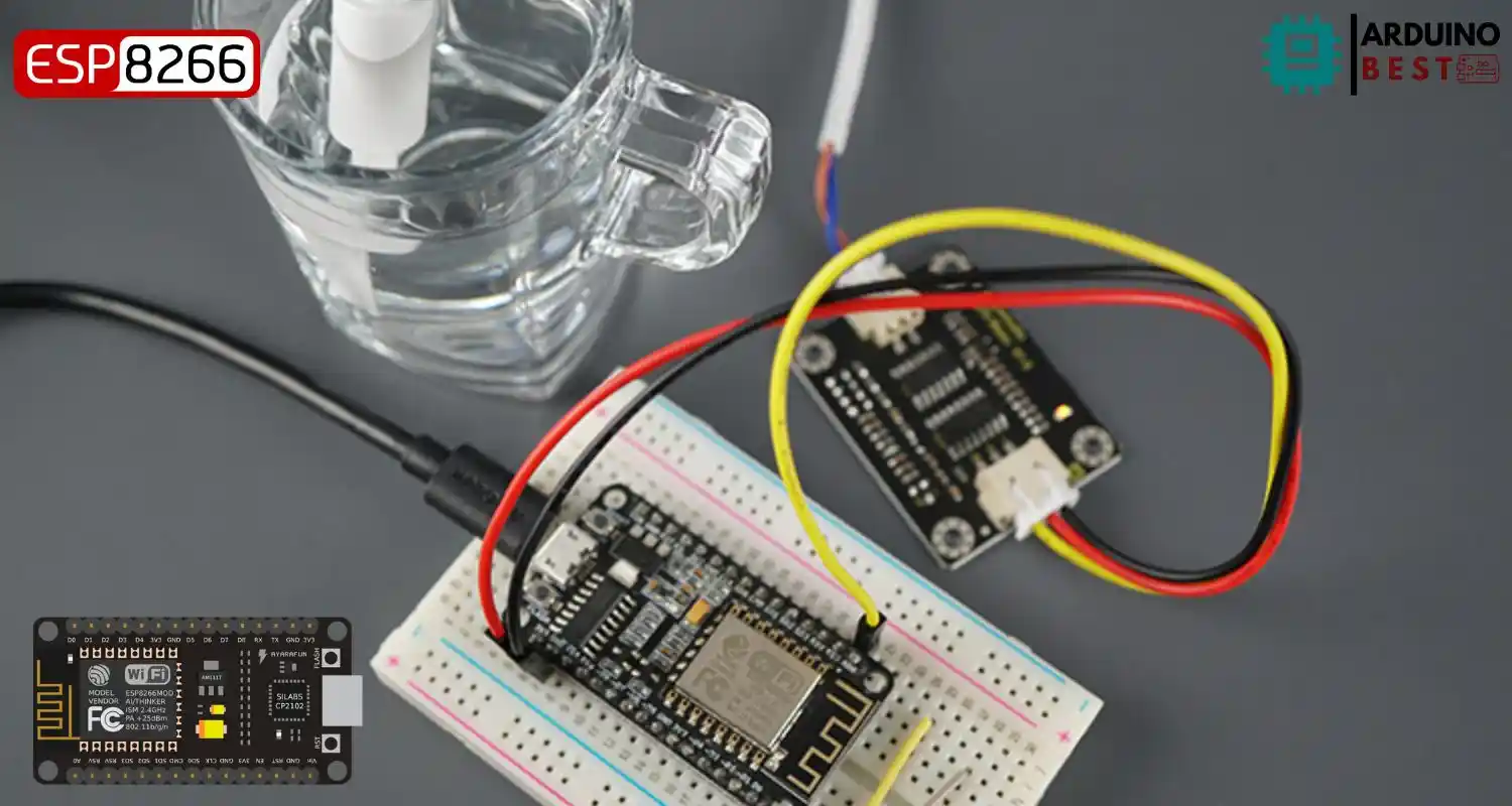
Circuit Diagram and Hardware Setup
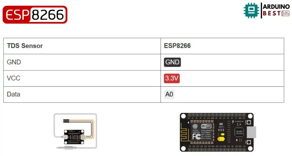
Wiring Instructions:
- Connect TDS sensor’s VCC to NodeMCU 3.3V
- GND to GND
- Analog output (Aout) to A0 pin on NodeMCU
- For DS18B20: connect Data pin to D2 with a 4.7kΩ pull-up resistor between Data and VCC
Tips for stable readings:
- Use shielded cables to minimize noise
- Keep sensor cables short
- Calibrate in a controlled environment
Programming the ESP8266 NodeMCU
Setting up Arduino IDE:
- Install ESP8266 board package
- Install required libraries:
ESP8266WiFi,OneWire,DallasTemperature, and optionallyBlynkfor remote monitoring
Sample Code Snippet:
#define TdsSensorPin A0
#define VREF 3.3              // analog reference voltage(Volt) of the ADC
#define SCOUNT  30            // sum of sample point

int analogBuffer[SCOUNT];     // store the analog value in the array, read from ADC
int analogBufferTemp[SCOUNT];
int analogBufferIndex = 0;
int copyIndex = 0;

float averageVoltage = 0;
float tdsValue = 0;
float temperature = 23;       // current temperature for compensation

// median filtering algorithm
int getMedianNum(int bArray[], int iFilterLen){
  int bTab[iFilterLen];
  for (byte i = 0; i<iFilterLen; i++)
  bTab[i] = bArray[i];
  int i, j, bTemp;
  for (j = 0; j < iFilterLen - 1; j++) {
    for (i = 0; i < iFilterLen - j - 1; i++) {
      if (bTab[i] > bTab[i + 1]) {
        bTemp = bTab[i];
        bTab[i] = bTab[i + 1];
        bTab[i + 1] = bTemp;
      }
    }
  }
  if ((iFilterLen & 1) > 0){
    bTemp = bTab[(iFilterLen - 1) / 2];
  }
  else {
    bTemp = (bTab[iFilterLen / 2] + bTab[iFilterLen / 2 - 1]) / 2;
  }
  return bTemp;
}

void setup(){
  Serial.begin(115200);
  pinMode(TdsSensorPin,INPUT);
}

void loop(){
  static unsigned long analogSampleTimepoint = millis();
  if(millis()-analogSampleTimepoint > 40U){     //every 40 milliseconds,read the analog value from the ADC
    analogSampleTimepoint = millis();
    analogBuffer[analogBufferIndex] = analogRead(TdsSensorPin);    //read the analog value and store into the buffer
    analogBufferIndex++;
    if(analogBufferIndex == SCOUNT){
      analogBufferIndex = 0;
    }
  }

  static unsigned long printTimepoint = millis();
  if(millis()-printTimepoint > 800U){
    printTimepoint = millis();
    for(copyIndex=0; copyIndex<SCOUNT; copyIndex++){
      analogBufferTemp[copyIndex] = analogBuffer[copyIndex];

      // read the analog value more stable by the median filtering algorithm, and convert to voltage value
      averageVoltage = getMedianNum(analogBufferTemp,SCOUNT) * (float)VREF / 1024.0;

      //temperature compensation formula: fFinalResult(25^C) = fFinalResult(current)/(1.0+0.02*(fTP-25.0));
      float compensationCoefficient = 1.0+0.02*(temperature-25.0);
      //temperature compensation
      float compensationVoltage=averageVoltage/compensationCoefficient;

      //convert voltage value to tds value
      tdsValue=(133.42*compensationVoltage*compensationVoltage*compensationVoltage - 255.86*compensationVoltage*compensationVoltage + 857.39*compensationVoltage)*0.5;

      //Serial.print("voltage:");
      //Serial.print(averageVoltage,2);
      //Serial.print("V   ");
      Serial.print("TDS Value:");
      Serial.print(tdsValue,0);
      Serial.println("ppm");
    }
  }
}
Calibration and Testing
TDS sensors must be calibrated using reference solutions to ensure accuracy. Follow these steps:
- Prepare calibration solutions (e.g., 300 ppm, 700 ppm)
- Submerge the sensor and record the analog readings
- Adjust the formula in the code to match the expected values
- Test with tap, filtered, and distilled water for verification
Data Visualization and Remote Monitoring
Using Blynk or ThingSpeak, you can visualize and log water quality data in real-time. Setup steps include:
- Create a Blynk project and get an Auth Token
- Modify the Arduino code to send TDS values via Wi-Fi
- Use widgets like Value Display and Gauge to show live data
You can learn how to build a DIY water quality monitor with Blynk for a complete example.
Applications and Use Cases
Practical applications of ESP8266 with TDS sensors include:
- Monitoring drinking water at home
- Maintaining water quality in fish tanks and aquariums
- Controlling nutrient levels in hydroponic systems
- Tracking water treatment performance in small-scale industrial setups
Troubleshooting Common Issues
Common problems and fixes:
- Fluctuating TDS readings: ensure cables are stable and insulated
- No data output: check serial monitor and board connections
- Incorrect values: recalibrate with fresh standard solutions
FAQs
What is the ideal TDS level for drinking water?
Under 500 ppm, according to WHO standards.
How often should I calibrate my TDS sensor?
Every 3 months or after sensor replacement.
Can I use multiple sensors with a single ESP8266?
Yes, use I2C or multiplexers for multiple analog devices.
How do temperature variations affect TDS readings?
Higher temperatures increase conductivity; use temperature compensation for accuracy.
Is it possible to monitor TDS levels continuously?
Yes, but avoid long-term immersion in harsh water to prevent sensor wear.
Conclusion
Pairing the ESP8266 NodeMCU with a TDS sensor enables affordable and scalable water quality monitoring. Whether for home use, agriculture, or educational projects, this setup empowers users to track water purity in real-time and take timely action.
Projects ESP8266 nodemcu :
1- ESP8266 NodeMCU: A Comprehensive Guide to IoT Development
2- Control LED with ESP8266 NodeMCU: A Beginner’s Guide
3- Integrating a Joystick with ESP8266 NodeMCU: A Comprehensive Guide
4- esp8266 nodemcu with Flame Sensor
5- ESP8266 NodeMCU with Heartbeat Sensor
6- ESP8266 NodeMCU with KY-027 Magic Cup Light
7- ESP8266 NodeMCU with Hall Magnetic Sensor
8- ESP8266 NodeMCU with relay module 5v
9- ESP8266 NodeMCU with Linear Hall Sensor