
Table of Contents
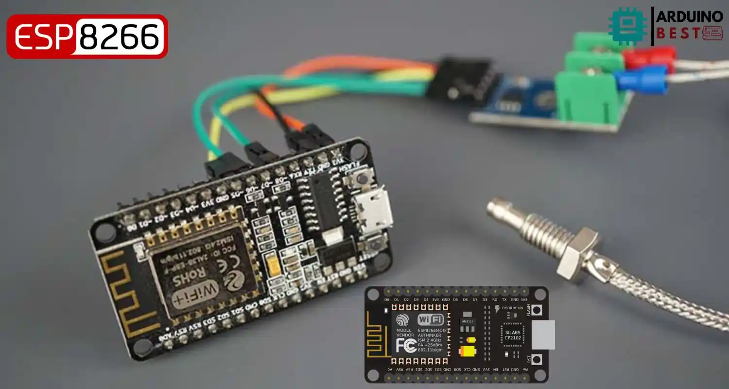
Accurate temperature sensing is essential for many industrial, scientific, and DIY applications. When dealing with extreme temperatures, K-Type thermocouples are a go-to solution due to their wide range and reliability. When combined with the MAX6675 amplifier and the ESP8266 NodeMCU, you get a powerful and low-cost solution for wireless temperature monitoring.
In this guide, you’ll learn how to interface a K-Type thermocouple with a MAX6675 and the ESP8266 NodeMCU, build a simple local web server for displaying real-time temperature data, and explore options for data logging and IoT integration. For those unfamiliar with the MAX6675 module, check out the MAX6675 Technical Specifications. To write code for this setup, we’ll also be using the Adafruit MAX6675 Arduino Library.
Understanding the Components
ESP8266 NodeMCU
- ESP8266 is a Wi-Fi-enabled microcontroller ideal for IoT projects
- Features include GPIO, ADC, PWM, and I2C/SPI support
- Easy to program using the Arduino IDE
- Supports web server functionality
K-Type Thermocouple
- Designed for high-temperature measurements
- Temperature range: −200°C to +1350°C
- Durable and cost-effective
- Generates a small voltage proportional to temperature, which needs amplification
MAX6675 Thermocouple Amplifier
- Converts thermocouple signal to readable digital data
- Uses SPI communication protocol
- Provides cold-junction compensation for accurate readings
- Outputs temperature in 0.25°C increments
Wiring and Hardware Setup
Required Components
- ESP8266 NodeMCU board
- MAX6675 thermocouple amplifier module
- K-Type thermocouple
- Jumper wires
- Breadboard (optional)
- Power source (USB or battery)
Wiring Diagram
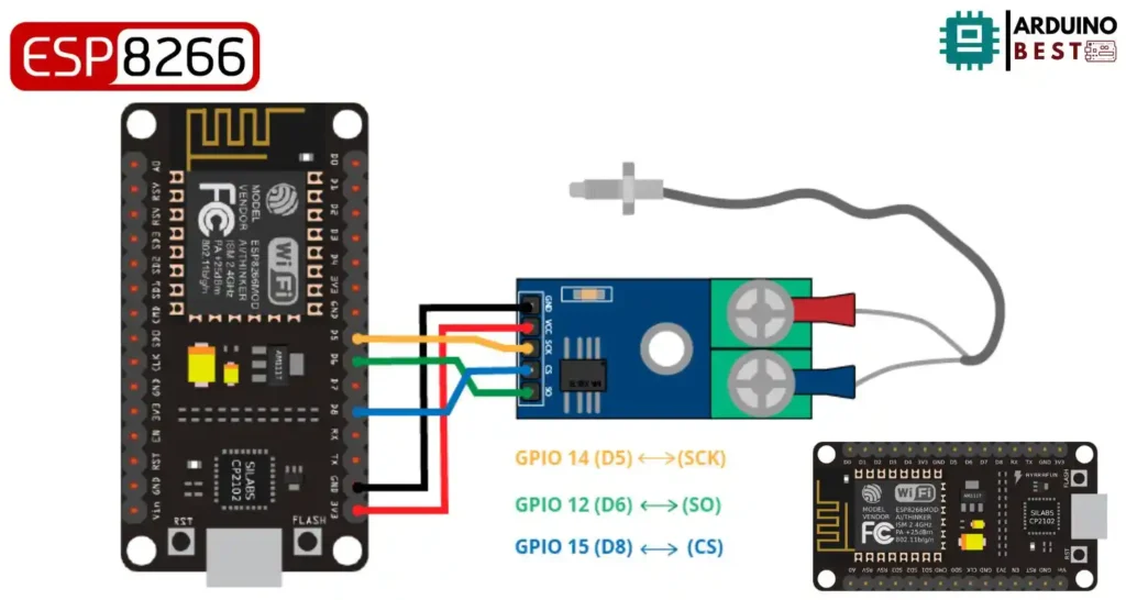
- VCC of MAX6675 → 3.3V on NodeMCU
- GND of MAX6675 → GND on NodeMCU
- SCK → D5
- CS → D8
- SO → D6
Tips
- Ensure solid connections to avoid inconsistent readings
- Use a proper power supply; unstable voltage can cause erratic sensor values
Software Configuration
Setting Up the Arduino IDE
- Download and install Arduino IDE
- Go to File > Preferences and add the ESP8266 board URL:
http://arduino.esp8266.com/stable/package_esp8266com_index.json - Open Boards Manager, install “esp8266 by ESP8266 Community”
- Select NodeMCU 1.0 (ESP-12E Module) from the board list
For deeper reference, visit the ESP8266 Arduino Core Guide
Installing the MAX6675 Library
- Open Library Manager and search for MAX6675
- Install “Adafruit MAX6675 Library”
- This library handles all SPI communication and simplifies reading temperatures
Sample Code
#include "max6675.h"

int thermoDO = 12;
int thermoCS = 15;
int thermoCLK = 14;

MAX6675 thermocouple(thermoCLK, thermoCS, thermoDO);

void setup() {
  Serial.begin(9600);

  Serial.println("MAX6675 test");
  // wait for MAX chip to stabilize
  delay(500);
}

void loop() {
  // basic readout test, just print the current temp

  Serial.print("C = ");
  Serial.println(thermocouple.readCelsius());
  Serial.print("F = ");
  Serial.println(thermocouple.readFahrenheit());

  // For the MAX6675 to update, you must delay AT LEAST 250ms between reads!
  delay(1000);
}
- Upload this sketch to your NodeMCU
- Open the Serial Monitor to view temperature data in real time
Displaying Data on an OLED
You can enhance the visual experience by connecting a 0.96″ I2C OLED screen.
Integration Steps
- Connect SDA to D1 and SCL to D2
- Use the
Adafruit_SSD1306andAdafruit_GFXlibraries - Display temperature readings dynamically alongside Serial Monitor
Creating a Web-Based Interface
Setting Up a Local Web Server
The ESP8266 can serve a basic HTML page using its Wi-Fi capability. Configure it as a web server to view temperature data from any browser on the same network.
#include "max6675.h"

int thermoDO = 12;
int thermoCS = 15;
int thermoCLK = 14;

MAX6675 thermocouple(thermoCLK, thermoCS, thermoDO);

void setup() {
  Serial.begin(9600);

  Serial.println("MAX6675 test");
  // wait for MAX chip to stabilize
  delay(500);
}

void loop() {
  // basic readout test, just print the current temp

  Serial.print("C = ");
  Serial.println(thermocouple.readCelsius());
  Serial.print("F = ");
  Serial.println(thermocouple.readFahrenheit());

  // For the MAX6675 to update, you must delay AT LEAST 250ms between reads!
  delay(1000);
}
- Modify the code above by adding the thermocouple object and logic from previous examples
- Access the web page by typing your NodeMCU’s IP address in your browser
Dynamic Updates with AJAX
- Use JavaScript and AJAX to update only the temperature portion of the page
- Reduces server load and improves user experience
Data Logging and IoT Integration
Logging temperature data is useful for analysis and monitoring over time.
SD Card Logging
- Connect an SD card module via SPI
- Log data with timestamps for later review
Cloud Platforms
- Platforms like Blynk IoT Integration allow remote access
- Display data on your smartphone using widgets and dashboards
- Configure triggers for alerts if temperature exceeds thresholds
Applications and Use Cases
- Industrial monitoring: Furnaces, kilns, and metalworking
- Home automation: HVAC systems, smart thermostats
- Scientific research: Chemical reactions, lab equipment monitoring
FAQs
How accurate is the MAX6675 with a K-Type thermocouple?
The module provides ±2°C accuracy for temperatures between 0°C and 700°C, which is sufficient for most non-critical applications.
Can the ESP8266 handle multiple thermocouples?
Yes, but it requires multiple MAX6675 modules and careful SPI chip-select management.
What is the maximum temperature range measurable?
With the K-Type thermocouple and MAX6675, you can measure from 0°C to 1024°C. The amplifier limits the top end, even though the thermocouple itself can go higher.
How to calibrate the thermocouple readings?
Calibration can be done by comparing readings to a known accurate thermometer and applying a correction factor in code.
Is it possible to use this setup without an internet connection?
Yes. The ESP8266 can host a web server on a local Wi-Fi network without internet access.
Conclusion
Using the ESP8266 NodeMCU with a K-Type thermocouple and MAX6675 amplifier is an effective way to build a wireless high-temperature monitoring system. This setup is compact, cost-efficient, and highly customizable, making it perfect for DIY makers, engineers, and hobbyists. With options for local display, web interface, and IoT connectivity, you can tailor it to a wide range of applications.
Experiment with the code, integrate it into your projects, and expand it with advanced features like cloud dashboards or voice assistants.
Projects ESP8266 nodemcu :
1- ESP8266 NodeMCU: A Comprehensive Guide to IoT Development
2- Control LED with ESP8266 NodeMCU: A Beginner’s Guide
3- Integrating a Joystick with ESP8266 NodeMCU: A Comprehensive Guide
4- esp8266 nodemcu with Flame Sensor
5- ESP8266 NodeMCU with Heartbeat Sensor
6- ESP8266 NodeMCU with KY-027 Magic Cup Light
7- ESP8266 NodeMCU with Hall Magnetic Sensor
8- ESP8266 NodeMCU with relay module 5v
9- ESP8266 NodeMCU with Linear Hall Sensor