

Table of Contents
Introduction
The integration of Internet of Things (IoT) technologies has led to innovative and engaging projects in the field of robotics. One of the most exciting applications of IoT is in creating remote-controlled cars that can be controlled via the internet. In this article, we’ll guide you through building a joystick-controlled car using the ESP8266 Wi-Fi module and the Blynk IoT platform. This project is a great way to dive into both hardware and software aspects of IoT, as well as explore motor control through a smartphone interface.
Why Choose ESP8266 and Blynk?
The ESP8266 is a popular choice for IoT projects due to its built-in Wi-Fi capabilities, small form factor, and affordability. When paired with the Blynk platform, you can easily control various IoT devices using a smartphone or tablet. The combination of these technologies allows you to create a wireless robot that can be controlled in real-time through a Blynk app, making it a perfect entry point for hobbyists and students interested in robotics and IoT.
For detailed tutorials and insights on how to get started with Blynk and the ESP8266, visit the Blynk Documentation and the ESP8266 Wiki.
Understanding the Components
Before diving into the project, let’s take a look at the key components involved in building the joystick-controlled car.
ESP8266 NodeMCU
The ESP8266 is a low-cost Wi-Fi microchip that makes it perfect for small IoT devices like our robot. It can be programmed using the popular Arduino IDE and is capable of connecting to a Wi-Fi network for seamless communication. The module features a compact design and provides GPIO pins for connecting sensors, motors, and other devices, making it versatile for a wide range of IoT projects.
Blynk IoT Platform
Blynk is an intuitive app and platform for building IoT projects. It offers a simple drag-and-drop interface for creating custom mobile dashboards to control hardware. By using the Blynk app, you can remotely control devices, monitor sensor readings, and send commands to your IoT project. It integrates seamlessly with the ESP8266, making it an ideal choice for our joystick-controlled car.
For more information about setting up your Blynk account and connecting it to hardware, check out the Blynk Documentation.
Joystick Module
The joystick module is a simple input device used for controlling movement in the car. It provides two axes of movement—X and Y—that allow you to control the car’s direction. The joystick communicates with the ESP8266, sending signals that determine the motor’s speed and direction.
L298N Motor Driver
The L298N motor driver is used to control the DC motors of the car. It allows for precise control of the motor’s direction and speed by sending signals from the ESP8266. This module is essential for ensuring smooth and efficient movement of the car.
DC Motors and Chassis
The DC motors provide the actual movement for the car. When connected to the motor driver, the motors can move the car forward, backward, and allow for turning. The chassis is the frame that houses the entire system, including the ESP8266, motor driver, and other components.
Setting Up the Hardware
The next step is to assemble the hardware components. Here’s how you can wire everything together to get the car ready for operation.
Assembling the Chassis
Start by assembling the car chassis. This is typically a plastic or metal frame that holds the wheels and the motors. Attach the DC motors to the chassis and secure the wheels onto the motor shafts.
Wiring the Components
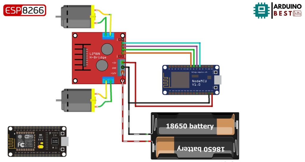
- ESP8266 to Motor Driver: Connect the ESP8266 to the L298N motor driver to control the motors. The ESP8266 will send signals to the motor driver to control the motors’ direction and speed.
- Motor Driver to Motors: Wire the DC motors to the output pins of the motor driver. The motor driver controls the flow of current to the motors, which determines their movement.
- Joystick to ESP8266: Connect the joystick module to the input pins on the ESP8266. The joystick will send analog signals to the ESP8266, which will interpret them and control the motors accordingly.
For further wiring instructions and diagrams, visit the Adafruit Motor Guide for more detailed information on motor wiring.
Power Supply
Make sure your power supply can handle the requirements of the ESP8266 and DC motors. You may need separate power sources for the microcontroller and the motors, as motors typically require more power than the ESP8266 can provide on its own.
Configuring the Blynk App
Once your hardware is set up, it’s time to configure the Blynk app to control the car remotely.
Creating a New Project
Open the Blynk app and create a new project. Select the ESP8266 as the device, and the app will generate an authentication token that you’ll need to use in your Arduino code.
Adding Widgets
- Joystick Widget: In the Blynk app, add the joystick widget to your dashboard. This will allow you to control the movement of the car from your phone.
- Virtual Pins: Use virtual pins to send and receive data between the app and the ESP8266. Assign virtual pins to control the motor direction and speed based on joystick inputs.
Generating Auth Token
Once your project is set up in the app, Blynk will provide you with an authentication token. This token will allow your ESP8266 to communicate securely with the app. Copy this token, as you’ll need it for the next step.
Programming the ESP8266
Now that your hardware and Blynk app are ready, it’s time to write the code for the ESP8266 to control the car.
#define BLYNK_PRINT Serial
#include <ESP8266WiFi.h>
#include <BlynkSimpleEsp8266.h>

#define RightMotorSpeed       D5   //14
#define RightMotorDir         D6   //12
#define LeftMotorSpeed        D7   //13
#define LeftMotorDir          D8   //15

char auth[] = "----------------";  //Blynk Authentication Token
char ssid[] = "-------";           //WIFI Name
char pass[] = "-------";           //WIFI Password

int minRange = 312;
int maxRange = 712;

int minspeed = 450;
int maxspeed = 1020;
int nospeed = 0;


void moveControl(int x, int y)
{
//Move Forward
    if(y >= maxRange && x >= minRange && x<= maxRange)
    {
        digitalWrite( RightMotorDir,HIGH);
        digitalWrite(LeftMotorDir,HIGH);
        analogWrite(RightMotorSpeed, maxspeed);
        analogWrite(LeftMotorSpeed , maxspeed);
    }


//Move Forward Right
    else if(x >= maxRange && y >= maxRange)
    {
        digitalWrite( RightMotorDir, HIGH);
        digitalWrite(LeftMotorDir,HIGH);
        analogWrite(RightMotorSpeed,minspeed);
        analogWrite(LeftMotorSpeed ,maxspeed);
    }

//Move Forward Left
    else if(x <= minRange && y >= maxRange)
    {
        digitalWrite( RightMotorDir,HIGH);
        digitalWrite(LeftMotorDir,HIGH);
        analogWrite(RightMotorSpeed,maxspeed);
        analogWrite(LeftMotorSpeed ,minspeed);
    }

//No Move
    else if(y < maxRange && y > minRange && x < maxRange && x > minRange)
    {
        analogWrite(RightMotorSpeed,nospeed);
        analogWrite(LeftMotorSpeed , nospeed);
    }

//Move Backward
    else if(y <= minRange && x >= minRange && x <= maxRange)
    {
        digitalWrite( RightMotorDir,LOW);
        digitalWrite(LeftMotorDir,LOW);
        analogWrite(RightMotorSpeed,maxspeed);
        analogWrite(LeftMotorSpeed ,maxspeed);
    }

//Move Backward Right
    else if(y <= minRange && x <= minRange)
    {
        digitalWrite( RightMotorDir,LOW);
        digitalWrite(LeftMotorDir,LOW);
        analogWrite(RightMotorSpeed,minspeed);
        analogWrite(LeftMotorSpeed ,maxspeed);
    }

//Move Backward Left
    else if(y <= minRange && x >= maxRange)
    {
        digitalWrite( RightMotorDir,LOW);
        digitalWrite(LeftMotorDir,LOW);
        analogWrite(RightMotorSpeed,maxspeed);
        analogWrite(LeftMotorSpeed ,minspeed);
    }
}

void setup()
{
    Serial.begin(9600);
    Blynk.begin(auth, ssid, pass);

    pinMode(RightMotorSpeed, OUTPUT);
    pinMode(LeftMotorSpeed , OUTPUT);
    pinMode( RightMotorDir, OUTPUT);
    pinMode(LeftMotorDir, OUTPUT);

    digitalWrite(RightMotorSpeed, LOW);
    digitalWrite(LeftMotorSpeed , LOW);
    digitalWrite( RightMotorDir, HIGH);
    digitalWrite(LeftMotorDir, HIGH);
}


void loop()
{
    Blynk.run();
}


BLYNK_WRITE(V1)
{
    int x = param[0].asInt();
    int y = param[1].asInt();
    moveControl(x,y);
}
Setting Up the Arduino IDE
Ensure that you have the correct libraries installed in the Arduino IDE to work with the ESP8266 and Blynk. Install the ESP8266 board package and the Blynk library through the Arduino Library Manager.
Writing the Code
- Including Libraries: Begin by including the necessary libraries in your code for the ESP8266 and Blynk.
- Defining Pins and Variables: Set up the input and output pins, such as the joystick pins and motor control pins.
- Connecting to Wi-Fi: Write the code to connect the ESP8266 to your Wi-Fi network.
- Blynk Authentication: Use the authentication token generated by Blynk in your code to connect the ESP8266 to the Blynk app.
- Reading Joystick Input: Implement code to read the joystick’s X and Y axis values and send them to the ESP8266.
- Motor Control Logic: Program the motor control logic to move the car based on the joystick input.
Uploading the Code
Upload the code to the ESP8266 using the Arduino IDE. Once uploaded, the car should be ready to control via the Blynk app.
Testing and Calibration
Once everything is set up, it’s time to test your car.
Initial Testing
Power up the car and connect it to the Blynk app. Test the connectivity between the app and the car to ensure that everything is working as expected.
Calibrating Joystick
Make sure the joystick is calibrated correctly. Adjust its neutral position so that the car remains stationary when the joystick is in the center.
Motor Testing
Test the motors to ensure that the car moves forward, backward, and turns as expected. Make sure the motors respond accurately to joystick input.
Enhancements and Customizations
After you’ve successfully built the basic joystick-controlled car, you can further improve the project by adding more features.
Speed Control
Implement speed control using PWM (Pulse Width Modulation) to allow for smoother and more variable movement.
Adding More Motors
Expand the project to a four-wheel drive system by adding additional motors for better maneuverability.
Obstacle Avoidance
Integrate ultrasonic sensors to avoid obstacles and make the car autonomous to some degree.
Camera Integration
Add a camera module to the car to stream live video to the Blynk app, providing a first-person view.
Voice Control
Explore adding voice control capabilities by integrating platforms like Google Assistant or Amazon Alexa.
Applications and Real-World Use Cases
This joystick-controlled car project has several potential applications.
Educational Tools
The project serves as a great educational tool for learning about IoT, robotics, and motor control.
Remote Surveillance
With added camera integration, the car can be used for remote surveillance in various environments.
Search and Rescue
The car can be used in search and rescue missions to navigate hazardous areas or search for objects in difficult-to-reach locations.
Entertainment
Use the car in interactive gaming setups, where players can control it as part of an augmented reality experience.
Conclusion
Building an ESP8266 Blynk Joystick Controlled Car is an exciting and rewarding project that combines IoT, robotics, and mobile control. This project serves as a great learning experience and can be expanded with numerous enhancements. By following the steps outlined in this article, you’ll gain hands-on experience with essential IoT concepts and hardware integration.
FAQs
- What is the ESP8266 used for in this project? The ESP8266 is used as the central controller to interface with the Blynk app and control the motors of the car.
- Can I control the car from anywhere in the world? Yes, as long as both the ESP8266 and the smartphone are connected to the internet, you can control the car from anywhere.
- What are some advanced features I can add to the car? You can add features like speed control, obstacle avoidance, camera integration, and even voice control for a more advanced project.
Projects ESP8266 nodemcu
1- ESP8266 NodeMCU: A Comprehensive Guide to IoT Development
2- Control LED with ESP8266 NodeMCU: A Beginner’s Guide
3- Integrating a Joystick with ESP8266 NodeMCU: A Comprehensive Guide
4- esp8266 nodemcu with Flame Sensor
5- ESP8266 NodeMCU with Heartbeat Sensor
6- ESP8266 NodeMCU with KY-027 Magic Cup Light
7- ESP8266 NodeMCU with Hall Magnetic Sensor
8- ESP8266 NodeMCU with relay module 5v
9- ESP8266 NodeMCU with Linear Hall Sensor