Table of Contents
Introduction
Measuring voltage is a fundamental aspect of electronics, from monitoring battery levels to testing circuit components. An Arduino voltmeter with an OLED display is a simple yet powerful tool that allows you to measure voltages accurately and display them in a visually appealing format.
In this guide, we’ll walk you through building a digital voltmeter using an Arduino and an OLED display. We will cover the necessary components, circuit assembly, coding, and calibration to ensure accurate voltage measurements.
Understanding Voltmeter Fundamentals
Before diving into the project, let’s cover some basics:
- A voltmeter measures the potential difference (voltage) between two points in an electrical circuit.
- There are two main types:
- Analog voltmeter: Uses a moving needle.
- Digital voltmeter: Displays readings numerically.
- Voltmeters are essential for electronics projects, from battery monitoring to debugging circuits.
Why Use an OLED Display with an Arduino?
An OLED display is an excellent choice for this project due to:
- High contrast and clarity: OLED displays provide sharp text and graphics.
- Low power consumption: Ideal for battery-operated devices.
- Easy interface with Arduino: Requires minimal wiring and code.
Project Overview
This project will:
- Measure DC voltage using an Arduino.
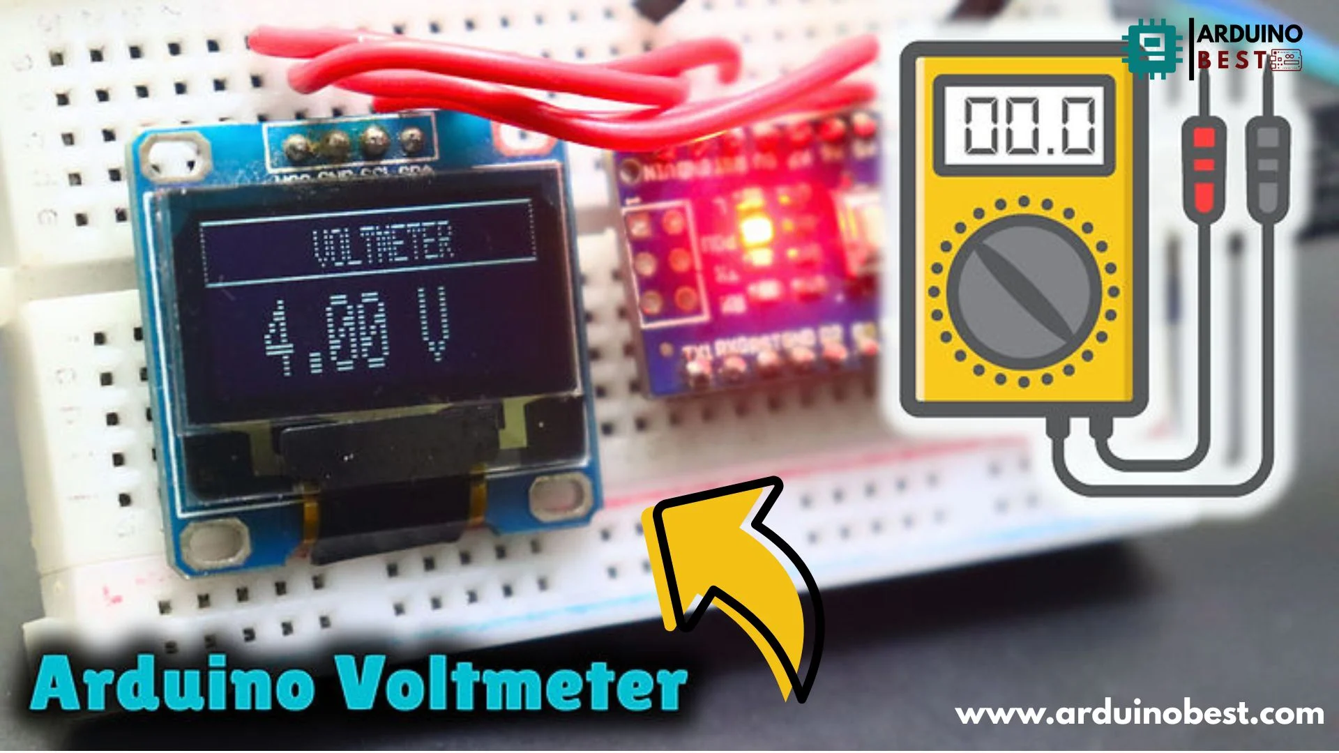
- Display real-time voltage readings on an OLED screen.
- Use a voltage divider to measure higher voltages safely.
Components and Tools Needed
To build this voltmeter, you’ll need:
Hardware Components
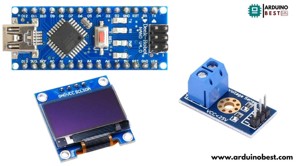
- Arduino Board (Uno, Nano, or Mega)
- Voltage Sensor
- 0.96″ OLED Display (SSD1306 or SH1106 controller)
- Breadboard and jumper wires

Software Requirements
- Arduino IDE
- Adafruit SSD1306 & GFX Libraries (for OLED display)
Circuit Design and Wiring

Understanding the Voltage Divider
The Arduino’s analog input pins can only handle a maximum of 5V. If you need to measure voltages higher than this, a voltage divider is required.
Formula:
V_out = (R2 / (R1 + R2)) * V_in
- R1 = 100kΩ
- R2 = 10kΩ
- V_in = Input voltage
- V_out = Output voltage (safe for Arduino)
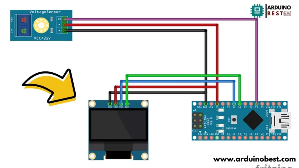
Connecting the OLED Display
| OLED Pin | Arduino Pin |
|---|---|
| VCC | 5V |
| GND | GND |
| SDA | A4 |
| SCL | A5 |
Arduino Code for the Voltmeter
Here’s the Arduino code to read the voltage and display it on the OLED screen:
#include <SPI.h>
#include <Wire.h>
#include <Adafruit_GFX.h>
#include <Adafruit_SSD1306.h>

#define OLED_RESET          A4

#define SSD1306_WHITE 1
#define SSD1306_BLACK 0
#define SSD1306_INVERSE 2

Adafruit_SSD1306 display(OLED_RESET);

int analogInput = A1;  //Sensor Input

void setup() {
  pinMode(analogInput, INPUT);

  Serial.begin(9600);
  Serial.println("VOLTMETER");

  display.begin(SSD1306_SWITCHCAPVCC, 0x3C);

  display.display();
  display.clearDisplay();

  display.display();

  display.drawRect(0, 0,  128 , 12, SSD1306_WHITE);
  display.setTextColor(SSD1306_WHITE, SSD1306_BLACK);
  display.setTextSize(1);
  display.setCursor(18, 3);
  display.println("    VOLTMETER   ");
  display.display();
}

float vout = 0.0;
float vin = 0.0;

float R1 = 30000.0;
float R2 = 7500.0;

int value = 0;

void loop() {

  value = analogRead(analogInput);
  vout = (value * 5.0) / 1024.0;
  vin = vout / (R2 / (R1 + R2));

  Serial.print("INPUT Voltage= ");
  Serial.println(vin, 2);

  display.setTextSize(2);
  display.setCursor(20, 15);
  display.println(vin, 2);
  display.setCursor(80, 15);
  display.println("V");
  display.display();

  delay(1000);


}
Calibrating the Voltmeter
To ensure accurate readings:
- Use a multimeter to compare measured voltage with the Arduino voltmeter.
- Adjust the voltage divider resistance if needed.
- Modify the calculation in the code to correct minor errors.
Troubleshooting Common Issues
1. OLED Display Not Working
- Check I2C connections (SDA to A4, SCL to A5).
- Ensure correct I2C address (0x3C or 0x3D).
2. Incorrect Voltage Readings
- Ensure proper resistor values in the voltage divider.
- Double-check the formula in the code.
3. Display Flickering or Freezing
- Use
display.clearDisplay()before updating the screen. - Reduce
delay()time for smoother updates.
Advanced Enhancements
- Expand voltage range: Use higher-value resistors in the divider.
- Add data logging: Save readings to an SD card.
- Wireless monitoring: Send data via Wi-Fi or Bluetooth.
- Battery-powered setup: Use a LiPo battery and voltage regulator.
Real-World Applications
- Battery monitoring in solar power projects.
- Sensor voltage measurements in IoT applications.
- DIY electronics and educational tools.
Frequently Asked Questions (FAQs)
1. How does the voltage divider work?
A voltage divider reduces input voltage so it can be measured safely by the Arduino’s 5V analog input.
2. Can this voltmeter measure AC voltage?
No, this setup only measures DC voltage. For AC measurement, use a rectifier circuit and an RMS-to-DC converter.
3. How can I increase the measurement range?
Use larger R1 and R2 resistor values in the voltage divider to handle higher input voltages.
4. Can I use an LCD instead of an OLED?
Yes, an LCD can be used, but an OLED display offers better contrast, readability, and power efficiency.
Conclusion
Building an Arduino voltmeter with an OLED display is an excellent way to enhance your electronics skills while creating a useful tool for voltage measurement. By following this guide, you can successfully assemble, code, and calibrate your voltmeter for precise readings.
Here we suggest other Arduino Projects:
1- Complete Guide for DHT11/DHT22 Humidity and Temperature Sensor With Arduino
2- DHT11 – Temperature and Humidity Sensor
3- DHT22 – Temperature and Humidity Sensor (more accurate than DHT11)
4- BMP180 – Barometric Pressure and Altitude Sensor
5- BMP280 – Barometric Pressure & Temperature Sensor
6- BME280 – Temperature, Humidity, and Pressure Sensor
7- Arduino Flex Sensor Controlled Robot Hand
8- Arduino ECG Heart Rate Monitor AD8232 Demo
9- Arduino NRF24L01 Wireless Joystick Robot Car
10- Arduino Force Sensor Anti-Theft Alarm System
11- Arduino NRF24L01 Transceiver Controlled Relay Light
12- Arduino Rotary Encoder Controlled LEDs: A Complete Guide

