
Table of Contents
Introduction
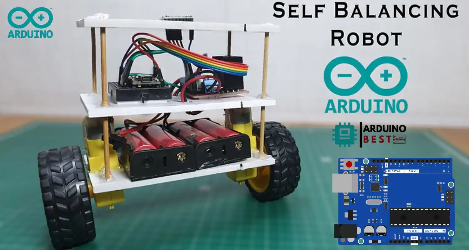
The Arduino UNO self-balancing robot is a fascinating project for anyone interested in robotics, automation, and DIY electronics. Building this type of robot introduces you to essential concepts like sensors, control systems, and motor drivers. In this guide, you’ll learn how to create your own two-wheeled self-balancing robot using Arduino UNO, from assembling the hardware to coding the control algorithm.
Understanding the Concept of Self-Balancing Robots
Self-balancing robots mimic the way humans maintain balance, using real-time sensor feedback and constant motor adjustments. They utilize a control system that reads orientation data and instantly corrects the robot’s position.
Some practical applications of self-balancing robots include:
- Personal transport devices like Segways
- Educational robotics kits
- Research prototypes for advanced robotics
To dive deeper into building a similar project, refer to this step-by-step Arduino self-balancing robot guide from Instructables. They provide a strong foundation for beginners and hobbyists alike.
A detailed tutorial from Circuit Digest also explains how the feedback system, consisting of sensors and motors, works together to stabilize the robot.
Components Required
To create your Arduino UNO self-balancing robot, gather the following components:
- Microcontroller: Arduino UNO R3
- Sensors: MPU6050 Gyroscope and Accelerometer Module
- Motor Driver: L298N or L293D Motor Driver Module
- Motors: Two DC geared motors with wheels
- Power Source: 9V battery or 7.4V Li-ion battery pack
- Chassis: Acrylic or metal frame
- Miscellaneous: Jumper wires, breadboard, screws, spacers
- Optional: Bluetooth module (HC-05) for remote control
Choosing the right components ensures that your robot remains stable and responsive during movement.
Circuit Diagram and Wiring
Correct wiring is crucial for proper functioning. Here’s a simple breakdown:
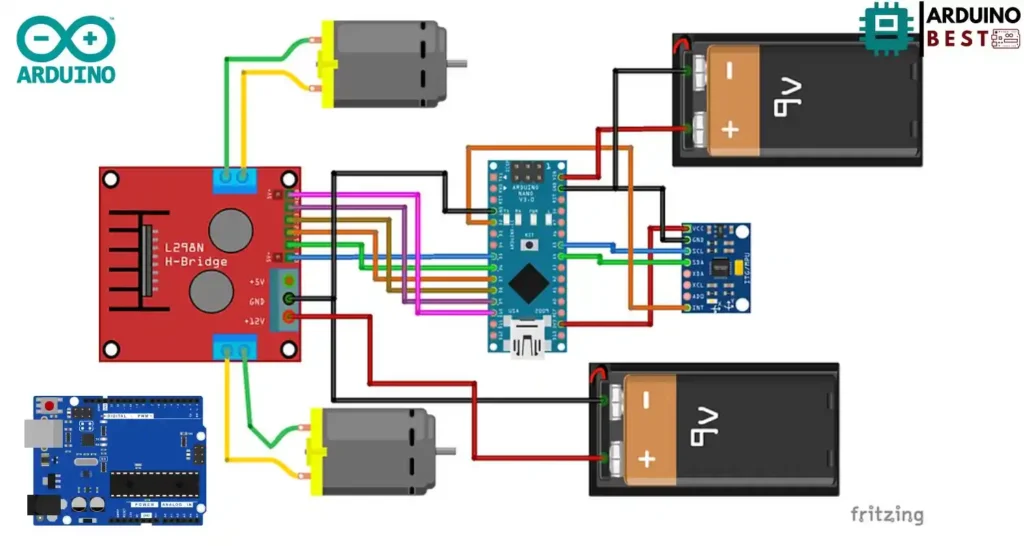
- Connect MPU6050 SDA and SCL pins to Arduino A4 and A5
- Connect motor inputs from the L298N driver to Arduino digital pins (e.g., D5, D6, D9, D10)
- Connect motors to output terminals of L298N
- Supply appropriate power to motors and Arduino
Some important tips:
- Double-check all ground (GND) connections
- Ensure that sensor orientation is upright
- Avoid loose connections that might cause signal disruptions
Programming the Arduino UNO
Once the hardware is set up, the next step is programming.
- Install Arduino IDE on your computer
- Install necessary libraries such as Wire.h and MPU6050.h
- Upload basic code to read MPU6050 sensor data
- Implement a PID control algorithm to adjust motor speed based on robot tilt
#include <PID_v1.h>
#include <LMotorController.h>
#include "I2Cdev.h"
#include "MPU6050_6Axis_MotionApps20.h"

#if I2CDEV_IMPLEMENTATION == I2CDEV_ARDUINO_WIRE
 #include "Wire.h"
#endif

#define MIN_ABS_SPEED 30

MPU6050 mpu;

// MPU control/status vars
bool dmpReady = false; // set true if DMP init was successful
uint8_t mpuIntStatus; // holds actual interrupt status byte from MPU
uint8_t devStatus; // return status after each device operation (0 = success, !0 = error)
uint16_t packetSize; // expected DMP packet size (default is 42 bytes)
uint16_t fifoCount; // count of all bytes currently in FIFO
uint8_t fifoBuffer[64]; // FIFO storage buffer

// orientation/motion vars
Quaternion q; // [w, x, y, z] quaternion container
VectorFloat gravity; // [x, y, z] gravity vector
float ypr[3]; // [yaw, pitch, roll] yaw/pitch/roll container and gravity vector

//PID
double originalSetpoint = 172.50;
double setpoint = originalSetpoint;
double movingAngleOffset = 0.1;
double input, output;

//adjust these values to fit your own design
double Kp = 60;
double Kd = 2.2;
double Ki = 270;
PID pid(&input, &output, &setpoint, Kp, Ki, Kd, DIRECT);

double motorSpeedFactorLeft = 0.6;
double motorSpeedFactorRight = 0.5;

//MOTOR CONTROLLER
int ENA = 5;
int IN1 = 6;
int IN2 = 7;
int IN3 = 9;
int IN4 = 8;
int ENB = 10;
LMotorController motorController(ENA, IN1, IN2, ENB, IN3, IN4, motorSpeedFactorLeft, motorSpeedFactorRight);

volatile bool mpuInterrupt = false; // indicates whether MPU interrupt pin has gone high
void dmpDataReady()
{
 mpuInterrupt = true;
}


void setup()
{
 // join I2C bus (I2Cdev library doesn't do this automatically)
 #if I2CDEV_IMPLEMENTATION == I2CDEV_ARDUINO_WIRE
 Wire.begin();
 TWBR = 24; // 400kHz I2C clock (200kHz if CPU is 8MHz)
 #elif I2CDEV_IMPLEMENTATION == I2CDEV_BUILTIN_FASTWIRE
 Fastwire::setup(400, true);
 #endif

 mpu.initialize();

 devStatus = mpu.dmpInitialize();

 // supply your own gyro offsets here, scaled for min sensitivity
 mpu.setXGyroOffset(220);
 mpu.setYGyroOffset(76);
 mpu.setZGyroOffset(-85);
 mpu.setZAccelOffset(1788); // 1688 factory default for my test chip

 // make sure it worked (returns 0 if so)
 if (devStatus == 0)
 {
 // turn on the DMP, now that it's ready
 mpu.setDMPEnabled(true);

 // enable Arduino interrupt detection
 attachInterrupt(0, dmpDataReady, RISING);
 mpuIntStatus = mpu.getIntStatus();

 // set our DMP Ready flag so the main loop() function knows it's okay to use it
 dmpReady = true;

 // get expected DMP packet size for later comparison
 packetSize = mpu.dmpGetFIFOPacketSize();

 //setup PID
 pid.SetMode(AUTOMATIC);
 pid.SetSampleTime(10);
 pid.SetOutputLimits(-255, 255);
 }
 else
 {
 // ERROR!
 // 1 = initial memory load failed
 // 2 = DMP configuration updates failed
 // (if it's going to break, usually the code will be 1)
 Serial.print(F("DMP Initialization failed (code "));
 Serial.print(devStatus);
 Serial.println(F(")"));
 }
}


void loop()
{
 // if programming failed, don't try to do anything
 if (!dmpReady) return;

 // wait for MPU interrupt or extra packet(s) available
 while (!mpuInterrupt && fifoCount < packetSize)
 {
 //no mpu data - performing PID calculations and output to motors
 pid.Compute();
 motorController.move(output, MIN_ABS_SPEED);

 }

 // reset interrupt flag and get INT_STATUS byte
 mpuInterrupt = false;
 mpuIntStatus = mpu.getIntStatus();

 // get current FIFO count
 fifoCount = mpu.getFIFOCount();

 // check for overflow (this should never happen unless our code is too inefficient)
 if ((mpuIntStatus & 0x10) || fifoCount == 1024)
 {
 // reset so we can continue cleanly
 mpu.resetFIFO();
 Serial.println(F("FIFO overflow!"));

 // otherwise, check for DMP data ready interrupt (this should happen frequently)
 }
 else if (mpuIntStatus & 0x02)
 {
 // wait for correct available data length, should be a VERY short wait
 while (fifoCount < packetSize) fifoCount = mpu.getFIFOCount();

 // read a packet from FIFO
 mpu.getFIFOBytes(fifoBuffer, packetSize);

 // track FIFO count here in case there is > 1 packet available
 // (this lets us immediately read more without waiting for an interrupt)
 fifoCount -= packetSize;

 mpu.dmpGetQuaternion(&q, fifoBuffer);
 mpu.dmpGetGravity(&gravity, &q);
 mpu.dmpGetYawPitchRoll(ypr, &q, &gravity);
 input = ypr[1] * 180/M_PI + 180;
 }
}
The main loop should:
- Read angle data from MPU6050
- Calculate the error between the desired and current position
- Adjust motor speeds accordingly to maintain balance
This programming phase is where most of the magic happens to make your Arduino UNO self-balancing robot functional.
PID Tuning for Stability
PID (Proportional, Integral, Derivative) control is the key to maintaining balance.
- Proportional (P): Reacts to the current error
- Integral (I): Accounts for accumulated past errors
- Derivative (D): Predicts future errors
Tips for PID tuning:
- Start with only the P term and gradually increase it
- Add D term to reduce overshooting
- Add I term slowly to eliminate steady-state errors
- Adjust until the robot stands upright with minor oscillations
Fine-tuning the PID values may take several iterations, so be patient.
Mechanical Assembly
After wiring and programming, it’s time to physically assemble the robot.
- Attach motors securely to the chassis
- Mount Arduino UNO and MPU6050 properly to avoid vibrations
- Distribute the weight evenly between the two wheels
- Organize wires neatly to prevent interference with wheels or sensors
A well-assembled frame significantly enhances the robot’s ability to balance.
Testing and Troubleshooting
Initial testing is critical:
- Ensure that the robot powers on properly
- Check that the MPU6050 is reading and transmitting data
- Observe how the robot behaves when you gently tilt it
Common problems and solutions:
- Robot falls immediately: Re-check wiring and sensor alignment
- Robot oscillates rapidly: Fine-tune PID values
- Motors spin but robot does not balance: Ensure correct motor connections and polarity
Troubleshooting systematically can save you a lot of time and frustration.
Enhancements and Upgrades
Once your basic self-balancing robot is working, consider adding new features:
- Bluetooth Control: Add an HC-05 module to control via smartphone
- Obstacle Avoidance: Integrate an ultrasonic sensor
- Advanced Stability: Use a more precise gyroscope
- Mobile Integration: Create a basic Android app for remote commands
Experimenting with upgrades is an excellent way to deepen your understanding of robotics.
FAQs
What is the purpose of the MPU6050 in the robot?
The MPU6050 provides accelerometer and gyroscope data necessary for calculating the robot’s tilt angle.
Can I use a different microcontroller instead of Arduino UNO?
Yes, boards like Arduino Nano or ESP32 can work, but wiring and coding will need modifications.
How do I know if my PID values are correct?
If the robot stands upright with minor oscillations and quickly returns to balance after a disturbance, your PID values are well-tuned.
Why is my robot not balancing even after uploading the code?
Possible reasons include wrong sensor orientation, incorrect PID tuning, or faulty wiring.
Is it necessary to use a motor driver?
Yes, a motor driver like L298N is essential to control the motors with the Arduino.
Conclusion
Building an Arduino UNO self-balancing robot is not just a fun DIY project; it’s a powerful way to understand essential concepts in robotics, control systems, and sensor integration. Through this project, you learn how devices like gyroscopes and accelerometers work together with PID control algorithms to maintain balance in real-time.
The process involves multiple stages — from gathering the right components, wiring the circuit correctly, programming the Arduino, to fine-tuning the PID values for optimal performance. Every step provides practical, hands-on experience that deepens your understanding of electronics and coding.
One of the great aspects of this project is its flexibility. After getting the basic robot to balance successfully, you can add features like Bluetooth control, obstacle detection, or even upgrade to more advanced microcontrollers for greater capabilities. Resources like the Instructables guide and tutorials from Circuit Digest provide further inspiration and detailed assistance.
If you encounter challenges along the way, troubleshooting and perseverance are part of the learning journey. With some patience and continuous improvement, your Arduino UNO self-balancing robot can become a showcase of your engineering skills and creativity.