Table of Contents
Introduction
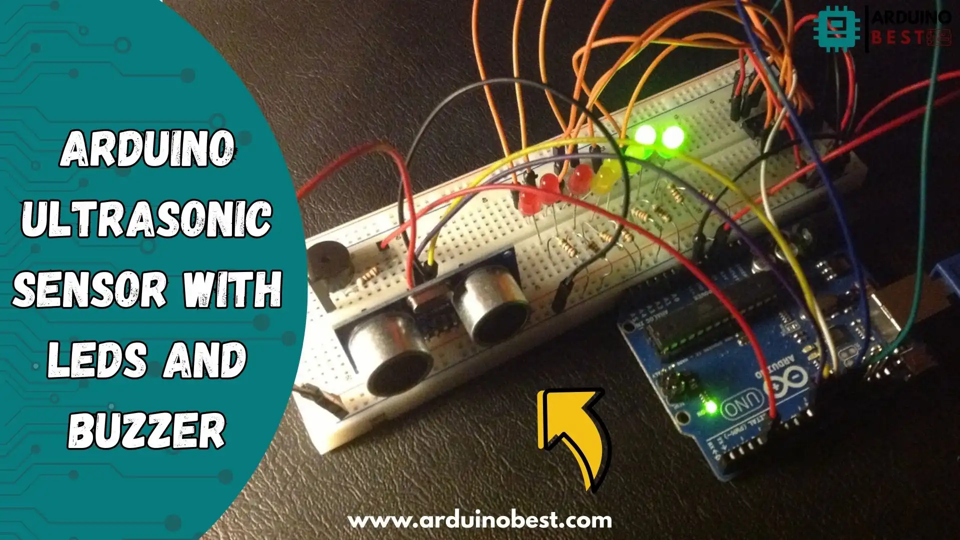
Using an ultrasonic sensor with LEDs and a buzzer in an Arduino project allows for innovative applications such as proximity alarms, obstacle detection, and automated response systems. This project is perfect for beginners and experienced developers alike, offering a hands-on way to learn about sensor integration and microcontroller programming.
One of the most commonly used sensors for distance measurement in Arduino projects is the HC-SR04 ultrasonic sensor. It works by emitting sound waves and measuring the time taken for the echo to return. This simple yet effective technology is widely used in various applications, from robotics to security systems. Learn more about the HC-SR04 ultrasonic sensor.
Understanding the Components
Before diving into the project, let’s break down the essential components:
- Arduino Board – The brain of the project that processes sensor data and controls the output components.
- HC-SR04 Ultrasonic Sensor – Measures distance using ultrasonic waves.
- LEDs – Provide visual feedback based on the detected distance.
- Buzzer – Emits an audible alarm when an object is too close.
For a step-by-step tutorial on integrating an ultrasonic sensor with LEDs and a buzzer, check out this detailed guide.
How the Ultrasonic Sensor Works
The HC-SR04 ultrasonic sensor measures distance based on sound wave travel time:
- The trigger pin sends a high signal for 10 microseconds.
- The sensor emits an ultrasonic sound wave.
- The wave reflects off an object and returns to the echo pin.
- The Arduino calculates distance using the formula:
Distance = (Time x Speed of Sound) / 2
Circuit Design and Assembly
Required Materials
- 1 x Arduino Uno
- 1 x HC-SR04 Ultrasonic Sensor
- 1 x Buzzer
- 3 x LEDs
- 3 x 330-ohm resistors
- Jumper wires
- Breadboard
Wiring Instructions

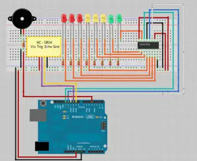
- Connect the VCC pin of the HC-SR04 sensor to the 5V pin on the Arduino.
- Connect the GND pin to the ground (GND) on the Arduino.
- Connect the trigger pin to digital pin 9.
- Connect the echo pin to digital pin 10.
- Attach the LEDs to digital pins 5, 6, and 7 through resistors.
- Connect the buzzer to digital pin 8.
Programming the Arduino
Setting Up the Environment
To begin coding, download and install the Arduino IDE and add the required libraries.
Code Example
int tonePin = 4;    //Tone - Red Jumper
int trigPin = 9;    //Trig - violet Jumper
int echoPin = 10;   //Echo - yellow Jumper
int clockPin = 11;  //IC Pin 11 - white Jumper
int latchPin = 12;  //IC Pin 12 - Blue Jumper
int dataPin = 13;   //IC Pin 14 - Green Jumper

byte possible_patterns[9] = {
B00000000,
B00000001,
B00000011,
B00000111,
B00001111,
B00011111,
B00111111,
B01111111,
B11111111,
};
int proximity=0;
int duration;
int distance;

void setup() {
  //Serial Port
  Serial.begin (9600);

  pinMode(trigPin, OUTPUT);
  pinMode(echoPin, INPUT);
  pinMode(clockPin, OUTPUT);
  pinMode(latchPin, OUTPUT);
  pinMode(dataPin, OUTPUT);
  pinMode(tonePin, OUTPUT);
}

void loop() {
  digitalWrite(latchPin, LOW);
  digitalWrite(trigPin, HIGH);
  delayMicroseconds(1000);
  digitalWrite(trigPin, LOW);
  duration = pulseIn(echoPin, HIGH);
  distance = (duration/2) / 29.1;

  /*if (distance >= 45 || distance <= 0){
    Serial.println("Out of range");
  }
  else {
    Serial.print(distance);
    Serial.println(" cm");
  }*/

  proximity=map(distance, 0, 45, 8, 0);
  //Serial.println(proximity);

  if (proximity <= 0){
    proximity=0;
  }
  else if (proximity >= 3 && proximity <= 4){
    tone(tonePin, 200000, 200);
  }
  else if (proximity >= 5 && proximity <= 6){
     tone(tonePin,5000, 200);
  }
  else if (proximity >= 7 && proximity <= 8){
    tone(tonePin, 1000, 200);
  }
  shiftOut(dataPin, clockPin, MSBFIRST, possible_patterns[proximity]);
  digitalWrite(latchPin, HIGH);


  delay(600);
  noTone(tonePin);
}
Uploading and Testing
- Connect your Arduino board to your computer.
- Upload the code via the Arduino IDE.
- Test the system by placing an object at varying distances.
Applications and Practical Uses
- Obstacle Avoidance – Used in robotics to detect obstacles.
- Smart Parking Systems – Detects available parking spots.
- Security Alarms – Triggers an alarm when an object moves close.
Troubleshooting Common Issues
- Sensor Not Responding – Check wiring connections.
- Inconsistent Readings – Ensure proper sensor calibration.
- Buzzer Not Activating – Verify that the threshold values in the code are correct.
FAQs
How do I calibrate the HC-SR04 ultrasonic sensor for accuracy?
Ensure the sensor is placed on a stable surface, and use a known distance reference to adjust calculations accordingly.
Can I use different types of buzzers?
Yes, but ensure the buzzer’s voltage and current ratings match the Arduino output.
How can I add more LEDs to this project?
You can use additional digital pins and modify the code to include more LEDs for more visual indicators.
What power source should I use?
You can use a 9V battery or a USB power supply for portability.
Conclusion
Integrating an ultrasonic sensor with LEDs and a buzzer in Arduino projects provides a simple yet powerful way to build smart automation and security systems. Whether you’re developing a proximity sensor, obstacle detection system, or an alarm-based alert, this setup is a great starting point for beginners and experienced makers alike.
By combining basic electronics with Arduino programming, you can create interactive systems that respond to real-world distances in real-time. The HC-SR04 ultrasonic sensor accurately measures distances, while the LEDs and buzzer provide immediate feedback—making it an ideal setup for DIY projects, robotics, and home automation.
This project can be expanded in several ways. Consider integrating an LCD display to show distance readings, or connecting it to an IoT platform to send alerts remotely. You can also enhance sensitivity by fine-tuning the sensor thresholds or using multiple ultrasonic sensors for a 360-degree detection system.
With endless possibilities for automation, security, and robotics, this project is a perfect way to start exploring the world of embedded systems. Get creative, experiment with new components, and take your Arduino skills to the next level! 🚀
Arduino Projects:
1- Complete Guide for DHT11/DHT22 Humidity and Temperature Sensor With Arduino
2- DHT11 – Temperature and Humidity Sensor
3- DHT22 – Temperature and Humidity Sensor (more accurate than DHT11)
4- BMP180 – Barometric Pressure and Altitude Sensor
5- BMP280 – Barometric Pressure & Temperature Sensor
6- BME280 – Temperature, Humidity, and Pressure Sensor
7- Arduino Flex Sensor Controlled Robot Hand
8- Arduino ECG Heart Rate Monitor AD8232 Demo
9- Arduino NRF24L01 Wireless Joystick Robot Car
10- Arduino Force Sensor Anti-Theft Alarm System
11- Arduino NRF24L01 Transceiver Controlled Relay Light
12- Arduino Rotary Encoder Controlled LEDs: A Complete Guide

