Table of Contents
Introduction to Arduino Timer Control Relay Devices
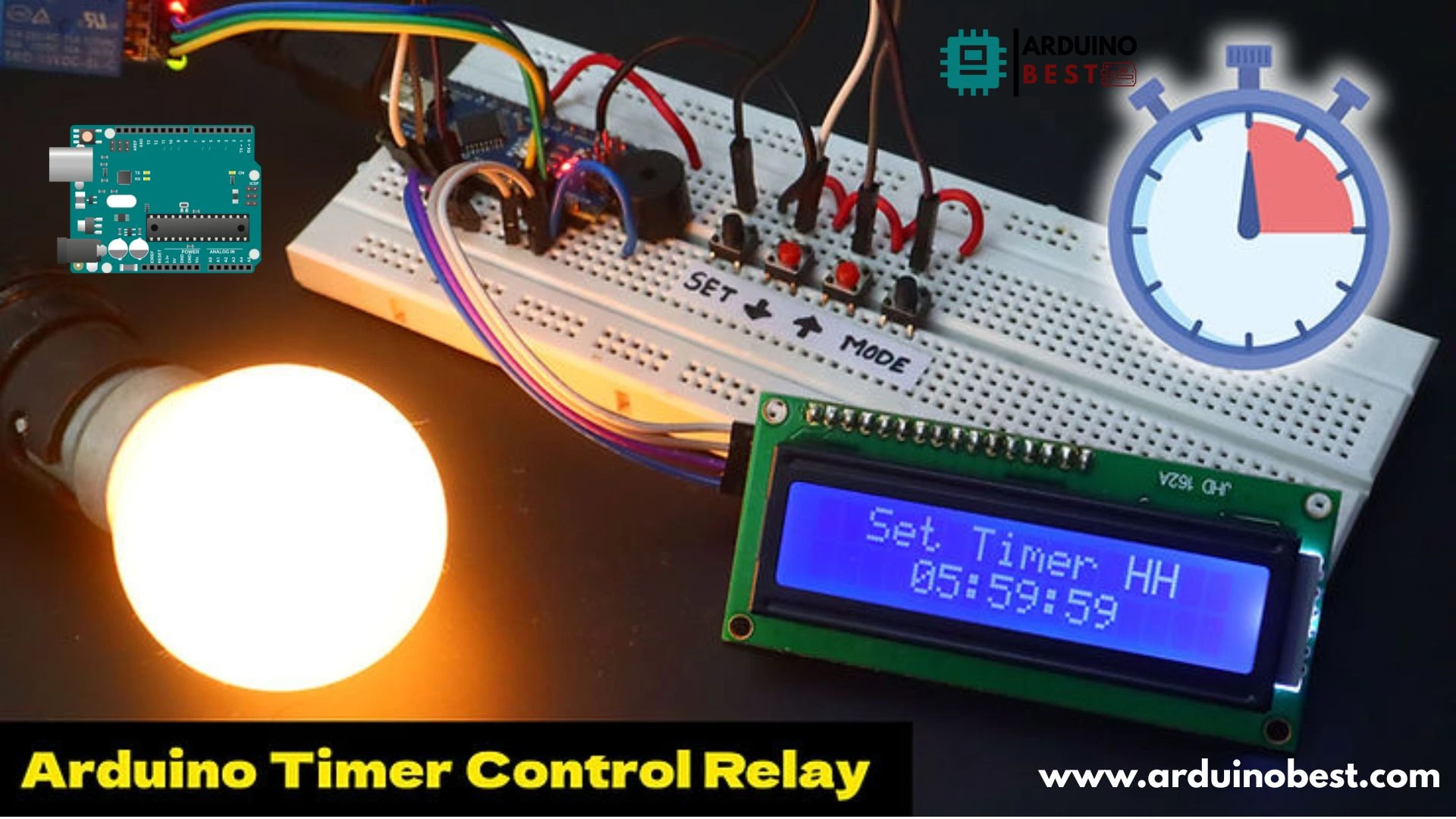
Arduino has revolutionized the world of automation, offering easy-to-use platforms for controlling electronic devices. One of the most powerful applications of Arduino is using a timer control relay to automate switching processes. These relays allow devices to turn on and off at predetermined times, making them useful for home automation, industrial control, and DIY projects.
From controlling LEDs to managing high-power electrical appliances, timer-based relays offer unmatched convenience. They are widely used in automated lighting, irrigation systems, and industrial equipment timing. Here’s a detailed guide on relay control to understand how relays work.
What is a Relay and How Does It Work?
A relay is an electrically operated switch used to control high-power devices using a low-power signal from Arduino. It consists of:
- Coil – Generates a magnetic field when powered.
- Contacts – Switches the electrical circuit on/off.
- Common (COM), Normally Open (NO), Normally Closed (NC) terminals – Defines how the relay operates.
Learn more about different types of relays and their uses to choose the best one for your project.
Why Use a Timer with a Relay?
Using a timer with a relay allows for precise control over when a device should turn on or off. Benefits include:
- Energy efficiency – Turns off unused devices automatically.
- Automation – Eliminates manual switching.
- Safety – Reduces electrical hazards.
Essential Components for an Arduino Timer Control Relay Setup
To build a timer-controlled relay project, you need:
- Arduino Board (Uno, Nano, or Mega)
- Relay Module (Single-channel or Multi-channel)
- RTC (Real-Time Clock) Module (DS1307 or DS3231)
- Display Unit (LCD or OLED)
- Input Devices (Push buttons, Rotary encoders)
- Wiring and Resistors
Step-by-Step Guide to Connecting a Timer-Controlled Relay to Arduino
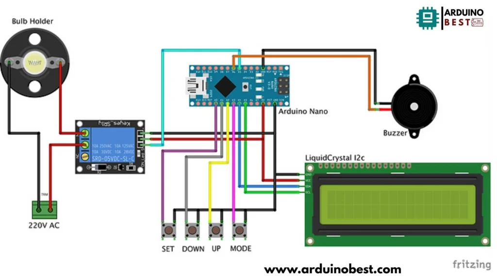
1. Circuit Connection
- Connect Arduino’s 5V and GND to the relay module.
- Attach the signal pin (IN) from the relay module to an Arduino digital pin (e.g., D7).
- Integrate the RTC module to ensure time-based triggering.
- Use an LCD display to show real-time information.

2. Coding the Timer-Based Relay System
#include <LiquidCrystal_I2C.h>  //https://github.com/fdebrabander/Arduino-LiquidCrystal-I2C-library
LiquidCrystal_I2C lcd(0x3F, 16, 2);  // LCD HEX address 0x3F -- change according to yours
#include "Countimer.h" //https://github.com/inflop/Countimer
Countimer tdown;
#include <EEPROM.h>

#define bt_set    A3
#define bt_up     A2
#define bt_down   A1
#define bt_start  A0

int time_s = 0;
int time_m = 0;
int time_h = 0;

int set = 0;
int flag1=0, flag2=0;

int relay = 5;
int buzzer = 6;

void setup() {
Serial.begin (9600);

pinMode(bt_set,   INPUT_PULLUP);
pinMode(bt_up,    INPUT_PULLUP);
pinMode(bt_down,  INPUT_PULLUP);
pinMode(bt_start, INPUT_PULLUP);

pinMode(relay, OUTPUT);
pinMode(buzzer, OUTPUT);

lcd.begin();
lcd.clear();
lcd.setCursor(0,0);
lcd.print("   Welcome To   ");
lcd.setCursor(0,1);
lcd.print("Countdown  Timer");
tdown.setInterval(print_time, 999);
eeprom_read();
delay(1000);
lcd.clear();
}

void print_time(){
time_s = time_s-1;
if(time_s<0){time_s=59; time_m = time_m-1;}
if(time_m<0){time_m=59; time_h = time_h-1;}
}

void tdownComplete(){Serial.print("ok");}

//tdown.stop();

void loop(){
tdown.run();

if(digitalRead (bt_set) == 0){
if(flag1==0 && flag2==0){flag1=1;
set = set+1;
if(set>3){set=0;}
delay(100);
}
}else{flag1=0;}

if(digitalRead (bt_up) == 0){
if(set==0){tdown.start(); flag2=1;}
if(set==1){time_s++;}
if(set==2){time_m++;}
if(set==3){time_h++;}
if(time_s>59){time_s=0;}
if(time_m>59){time_m=0;}
if(time_h>99){time_h=0;}
if(set>0){eeprom_write();}
delay(200);
}

if(digitalRead (bt_down) == 0){
if(set==0){tdown.stop(); flag2=0;}
if(set==1){time_s--;}
if(set==2){time_m--;}
if(set==3){time_h--;}
if(time_s<0){time_s=59;}
if(time_m<0){time_m=59;}
if(time_h<0){time_h=99;}
if(set>0){eeprom_write();}
delay(200);
}

if(digitalRead (bt_start) == 0){ flag2=1;
  eeprom_read();
  digitalWrite(relay, HIGH);
  tdown.restart();
  tdown.start();
}

lcd.setCursor(0,0);
if(set==0){lcd.print("      Timer     ");}
if(set==1){lcd.print("  Set Timer SS  ");}
if(set==2){lcd.print("  Set Timer MM  ");}
if(set==3){lcd.print("  Set Timer HH  ");}

lcd.setCursor(4,1);
if(time_h<=9){lcd.print("0");}
lcd.print(time_h);
lcd.print(":");
if(time_m<=9){lcd.print("0");}
lcd.print(time_m);
lcd.print(":");
if(time_s<=9){lcd.print("0");}
lcd.print(time_s);
lcd.print("   ");

if(time_s==0 && time_m==0 && time_h==0 && flag2==1){flag2=0;
tdown.stop();
digitalWrite(relay, LOW);
digitalWrite(buzzer, HIGH);
delay(300);
digitalWrite(buzzer, LOW);
delay(200);
digitalWrite(buzzer, HIGH);
delay(300);
digitalWrite(buzzer, LOW);
delay(200);
digitalWrite(buzzer, HIGH);
delay(300);
digitalWrite(buzzer, LOW);
}

if(flag2==1){digitalWrite(relay, HIGH);}
else{digitalWrite(relay, LOW);}

delay(1);
}

void eeprom_write(){
EEPROM.write(1, time_s);
EEPROM.write(2, time_m);
EEPROM.write(3, time_h);
}

void eeprom_read(){
time_s =  EEPROM.read(1);
time_m =  EEPROM.read(2);
time_h =  EEPROM.read(3);
}
3. Upload and Test
- Upload the code to your Arduino.
- Ensure the relay activates at the correct time.
- Modify settings for different time schedules.
Common Issues and Troubleshooting
Relay Not Switching?
- Verify wiring connections.
- Check the Arduino pin output with a multimeter.
- Ensure the relay is receiving proper power.
RTC Module Giving Incorrect Time?
- Use
rtc.adjust(DateTime(F(__DATE__), F(__TIME__)));to set the time. - Keep the backup battery in the module to retain settings.
Advanced Applications and Enhancements
- Multiple Relay Control – Automate several devices with one Arduino.
- Remote Control – Integrate Bluetooth/WiFi for remote switching.
- Logging Relay Activity – Store activation logs for monitoring.
Frequently Asked Questions (FAQs)
Can I use a timer relay without an RTC module?
Yes, by using the millis() function, but an RTC module ensures accuracy.
Can Arduino handle high-voltage appliances?
No, always use a relay with an appropriate rating for high-voltage loads.
How do I extend the relay’s lifespan?
Use solid-state relays (SSRs) for durability in frequent switching applications.
Conclusion
Using Arduino Timer Control Relay Devices simplifies automation and enhances efficiency. By following this guide, you can create a reliable timer-controlled system for various applications. Explore different relay modules and experiment with home automation projects to master the possibilities!
Here we suggest other Arduino Projects:
1- Complete Guide for DHT11/DHT22 Humidity and Temperature Sensor With Arduino
2- DHT11 – Temperature and Humidity Sensor
3- DHT22 – Temperature and Humidity Sensor (more accurate than DHT11)
4- BMP180 – Barometric Pressure and Altitude Sensor
5- BMP280 – Barometric Pressure & Temperature Sensor
6- BME280 – Temperature, Humidity, and Pressure Sensor
7- Arduino Flex Sensor Controlled Robot Hand
8- Arduino ECG Heart Rate Monitor AD8232 Demo
9- Arduino NRF24L01 Wireless Joystick Robot Car
10- Arduino Force Sensor Anti-Theft Alarm System
11- Arduino NRF24L01 Transceiver Controlled Relay Light
12- Arduino Rotary Encoder Controlled LEDs: A Complete Guide

