Table of Contents
Introduction
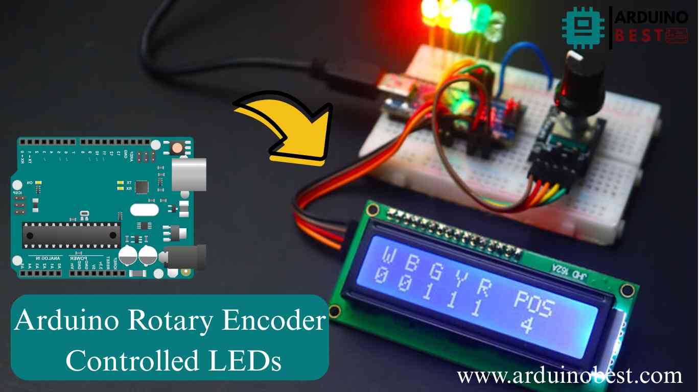
If you’re looking to enhance your Arduino projects, integrating a rotary encoder to control LEDs is a great way to experiment with user inputs. This guide will walk you through how to use a rotary encoder with Arduino to control LED brightness, sequences, and even RGB color variations.
By the end of this tutorial, you’ll learn:
- What a rotary encoder is and how it works
- How to connect a rotary encoder with Arduino
- How to program Arduino to read encoder inputs and control LEDs
- Common troubleshooting tips
For a deeper understanding of rotary encoders and how they work with Arduino, check out this Arduino Rotary Encoder LED Control Tutorial.
Understanding Rotary Encoders
What is a Rotary Encoder?
A rotary encoder is an electromechanical device that converts the angular position of a shaft into digital signals. Unlike potentiometers, rotary encoders provide infinite rotation, making them useful for precise control applications.
How Do Rotary Encoders Work?
Rotary encoders operate using:
- Quadrature encoding: Two output signals (A and B) determine direction and position.
- Push-button function: Some encoders include a built-in push button for extra control.
If you’re new to rotary encoders, you might find this detailed guide on how encoders work useful.
Components and Tools Required
Hardware Components
To follow this tutorial, you’ll need:
- Arduino (e.g., Arduino Uno)
- Rotary encoder module
- LEDs (single or RGB)
- Resistors (for current-limiting)
- Breadboard and jumper wires
Software Tools
- Arduino IDE (to write and upload code)
- Rotary Encoder Library (optional, for easier signal handling)
Circuit Design and Connections
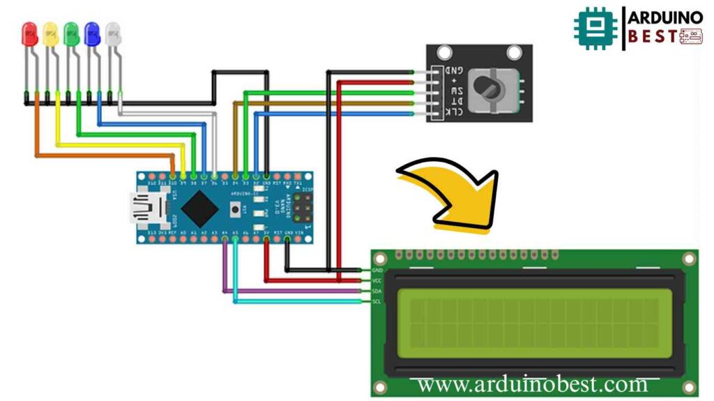
Wiring the Rotary Encoder to Arduino

| Encoder Pin | Arduino Pin |
|---|---|
| GND | GND |
| VCC | 5V |
| CLK | D2 |
| DT | D3 |
| SW | D4 (optional) |
Connecting LEDs
- Single LED: Connect to a PWM pin for brightness control.
- Multiple LEDs: Assign each LED to a different Arduino pin.
- RGB LED: Connect Red, Green, and Blue pins to PWM pins for color mixing.
Programming the Arduino
Reading Rotary Encoder Inputs
To accurately read rotary encoder signals:
- Use interrupts to capture real-time movement.
- Implement debouncing to eliminate noise.
Basic Arduino Code for Rotary Encoder and LED Control
#include <LiquidCrystal_I2C.h> //SDA = A4, SCL = A5
LiquidCrystal_I2C lcd(0x3F, 16, 2);

const int RotaryCLK = 2; //CLK pin on the rotary encoder
const int RotaryDT = 4; //DT pin on the rotary encoder
const int RotarySW = 3; //SW pin on the rotary encoder (Button function)
int ButtonCounter = 0; //counts the button clicks
int RotateCounter = 0; //counts the rotation clicks
bool rotated = true; //info of the rotation
bool ButtonPressed = false; //info of the button
int CLKNow;
int CLKPrevious;
int DTNow;
int DTPrevious;
float TimeNow1;
float TimeNow2;

const int whiteLED = 6;
const int blueLED = 7;
const int greenLED = 8;
const int yellowLED = 9;
const int redLED = 10;

bool whiteLEDStatus = false;
bool blueLEDStatus = false;
bool greenLEDStatus = false;
bool yellowLEDStatus = false;
bool redLEDStatus = false;

void setup()
{

  lcd.begin();                      // initialize the lcd
  lcd.backlight();
  lcd.setCursor(0,0); //Defining position to write from first row, first column .
  lcd.print("W B G Y R  POS");
  lcd.setCursor(0,1); //second line, 1st block
  lcd.print("0 0 0 0 0   0"); //You can write 16 Characters per line .
  delay(3000); //wait 3 sec
   pinMode(2, INPUT_PULLUP);
   pinMode(3, INPUT_PULLUP);
   pinMode(4, INPUT_PULLUP);
   pinMode(whiteLED, OUTPUT); //white LED
   pinMode(blueLED, OUTPUT); //blue LED
   pinMode(greenLED, OUTPUT); //green LED
   pinMode(yellowLED, OUTPUT); //yellow LED
   pinMode(redLED, OUTPUT); //red LED
   digitalWrite(whiteLED, LOW);
   digitalWrite(blueLED, LOW);
   digitalWrite(greenLED, LOW);
   digitalWrite(yellowLED, LOW);
   digitalWrite(redLED, LOW);

  CLKPrevious = digitalRead(RotaryCLK);
  DTPrevious = digitalRead(RotaryDT);

  attachInterrupt(digitalPinToInterrupt(RotaryCLK), rotate, CHANGE);
  attachInterrupt(digitalPinToInterrupt(RotarySW), buttonPressed, FALLING); //either falling or rising but never "change".

  TimeNow1 = millis(); //Start timer 1
}


void loop()
{
  printLCD();
  ButtonChecker();
}

void buttonPressed()
{
  //This timer is a "software debounce". It is not the most effective solution, but it works
  TimeNow2 = millis();
  if(TimeNow2 - TimeNow1 > 500)
  {
    ButtonPressed = true;
  }
  TimeNow1 = millis();  //"reset" timer; the next 500 ms is counted from this moment
}

void rotate()
{
  CLKNow = digitalRead(RotaryCLK); //Read the state of the CLK pin

  // If last and current state of CLK are different, then a pulse occurred
    if (CLKNow != CLKPrevious  && CLKNow == 1)
    {
    // If the DT state is different than the CLK state then
    // the encoder is rotating CCW so increase
      if (digitalRead(RotaryDT) != CLKNow)
      {
      RotateCounter++;

      if(RotateCounter > 4)
      {
       RotateCounter = 0;
      }

      }
      else
      {
      RotateCounter--;

      if(RotateCounter < 0)
      {
        RotateCounter = 4;
      }

      }
    }

  CLKPrevious = CLKNow;  // Store last CLK state
  rotated = true;
}


void printLCD()
{
    if(rotated == true) //refresh the CLK
    {
      lcd.setCursor(12,1);
      lcd.print(RotateCounter);
      rotated = false;
    }

}


void ButtonChecker() //this is basically the menu part. keep track of the buttonpressed and rotatecounter for navigation
{
  if(ButtonPressed == true)
  {
    switch(RotateCounter)
    {
      case 0:
      if(whiteLEDStatus == false)
      {
        whiteLEDStatus = true;
        digitalWrite(whiteLED, HIGH); //white LED is turned ON
      }
      else
      {
        whiteLEDStatus = false;
        digitalWrite(whiteLED, LOW); //white LED is turned OFF
      }

      lcd.setCursor(0,1); // Defining positon to write from second row, first column .
      lcd.print(whiteLEDStatus);

      break;

      case 1:
      if(blueLEDStatus == false)
      {
        blueLEDStatus = true;
        digitalWrite(blueLED, HIGH);

      }
      else
      {
        blueLEDStatus = false;
        digitalWrite(blueLED, LOW);
      }

      lcd.setCursor(2,1); // Defining positon to write from second row, first column .
      lcd.print(blueLEDStatus);
      break;

      case 2:
      if(greenLEDStatus == false)
      {
        greenLEDStatus = true;
        digitalWrite(greenLED, HIGH);

      }
      else
      {
        greenLEDStatus = false;
        digitalWrite(greenLED, LOW);
      }

      lcd.setCursor(4,1); // Defining positon to write from second row, first column .
      lcd.print(greenLEDStatus);
      break;

      case 3:
      if(yellowLEDStatus == false)
      {
        yellowLEDStatus = true;
        digitalWrite(yellowLED, HIGH);
      }
      else
      {
        yellowLEDStatus = false;
        digitalWrite(yellowLED, LOW);
      }
      lcd.setCursor(6,1); // Defining positon to write from second row, first column .
      lcd.print(yellowLEDStatus);

      break;

      case 4:
      if(redLEDStatus == false)
      {
        redLEDStatus = true;
        digitalWrite(redLED, HIGH);

      }
      else
      {
        redLEDStatus = false;
        digitalWrite(redLED, LOW);
      }

      lcd.setCursor(8,1); // Defining positon to write from second row, first column .
      lcd.print(redLEDStatus);
      break;
    }
  }
  ButtonPressed = false; //reset this variable
}
Explanation of Code
- Reads rotary encoder signals and detects rotation direction.
- Maps the rotary encoder value to adjust LED brightness.
Practical Applications and Examples
1. LED Brightness Control
- Rotate the encoder to increase or decrease brightness.
2. LED Chaser Effect
- Use the rotary encoder to cycle through LEDs in a sequence.
3. RGB LED Color Control
- Change colors dynamically based on rotary encoder input.
4. LED Strip Control
- Adjust LED brightness or effects on a strip using the encoder.
Troubleshooting Common Issues
1. Inaccurate Encoder Readings
- Use hardware or software debouncing.
2. LED Flickering
- Check PWM signals for stability.
3. Power Supply Issues
- Ensure sufficient current and voltage supply.
FAQs
How do I debounce a rotary encoder in Arduino?
Use software debouncing techniques like checking state changes within a time threshold.
Can I control multiple LEDs with a single rotary encoder?
Yes, by mapping different encoder positions to LED outputs.
What are the limitations of using rotary encoders with Arduino?
- Requires interrupt-based reading for accuracy.
- Limited by the resolution of the encoder.
How can I implement a push-button function in a rotary encoder?
Use the SW pin to detect button presses for additional controls.
Conclusion
You’ve now learned how to use a rotary encoder with Arduino to control LEDs effectively. Experiment with different LED setups and try integrating this into bigger projects like home automation or gaming interfaces.
If you want to explore more, check out this in-depth guide on rotary encoders.
Happy coding!
Here we suggest other Arduino Projects:
1- Complete Guide for DHT11/DHT22 Humidity and Temperature Sensor With Arduino
2- DHT11 – Temperature and Humidity Sensor
3- DHT22 – Temperature and Humidity Sensor (more accurate than DHT11)
4- BMP180 – Barometric Pressure and Altitude Sensor
5- BMP280 – Barometric Pressure & Temperature Sensor
6- BME280 – Temperature, Humidity, and Pressure Sensor
7- Arduino Flex Sensor Controlled Robot Hand
8- Arduino ECG Heart Rate Monitor AD8232 Demo
9- Arduino NRF24L01 Wireless Joystick Robot Car
10- Arduino Force Sensor Anti-Theft Alarm System11- Arduino NRF24L01 Transceiver Controlled Relay Light

