Table of Contents
Introduction
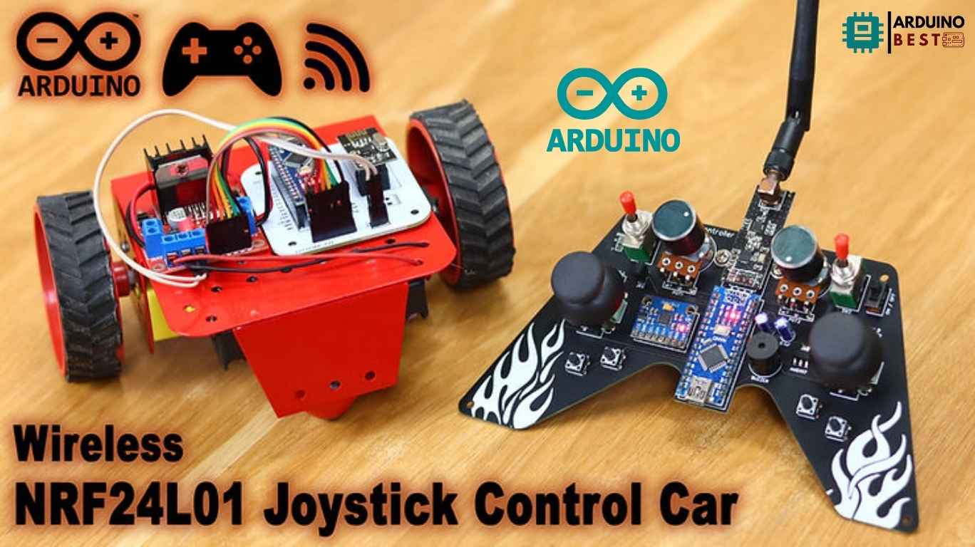
Building an Arduino NRF24L01 Wireless Joystick Robot Car is an exciting way to explore wireless communication and robotics. This project allows you to control a robot car remotely using a joystick and an NRF24L01 transceiver module. It’s an excellent learning experience for hobbyists and students interested in robotics, Arduino programming, and wireless technologies.
This guide will walk you through the necessary components, hardware setup, programming, testing, and troubleshooting to help you build your own wireless joystick-controlled robot car.
Understanding the Components
Before diving into the setup, let’s explore the essential components involved in this project:
Arduino Microcontroller
- The brain of the robot car.
- Processes input from the joystick and controls the motors accordingly.
- Compatible with various sensors and modules.
NRF24L01 Transceiver Module
- Enables wireless communication between the joystick controller and the robot car.
- Operates in the 2.4GHz frequency range, providing long-range and low-power consumption.
- Learn more about NRF24L01 on DroneBot Workshop.
Joystick Module
- Captures movement and converts it into electrical signals.
- Sends X and Y axis values to the Arduino, which are mapped to motor control.
Motor Driver (L298N)
- Controls the direction and speed of the motors.
- Allows smooth forward, backward, left, and right movements.
- More details on motor drivers can be found on SparkFun.
Power Supply
- Ensures the proper voltage and current for the robot car.
- Typically uses rechargeable batteries or a Li-ion pack.
How the System Works
The working principle of the wireless joystick-controlled robot car is as follows:
- The joystick module sends signals to the transmitter Arduino.
- The NRF24L01 module transmits this data wirelessly to the receiver Arduino on the robot car.
- The receiver interprets the signals and sends commands to the motor driver.
- The motor driver moves the car in the appropriate direction based on the joystick’s input.
Setting Up the Hardware
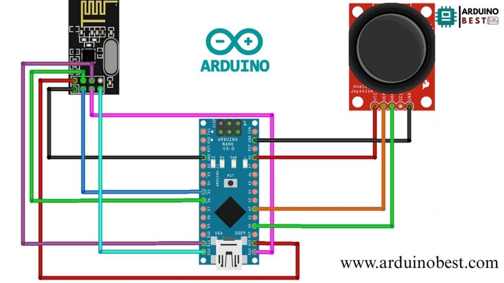
Transmitter (Joystick Controller) Setup
- Connect the joystick module to the Arduino.
- Integrate the NRF24L01 transceiver.
- Power the system with an appropriate voltage source.

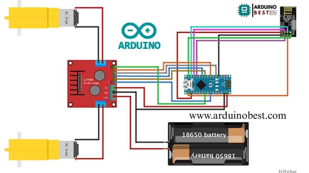
Receiver (Robot Car) Setup
- Connect the NRF24L01 module to the Arduino.
- Wire the motor driver to the Arduino and motors.
- Power the setup with a battery pack.
- Secure connections and use capacitors to ensure stable NRF24L01 operation.

Programming the Arduino
Transmitter Code
- Reads analog signals from the joystick.
- Maps values to motor control signals.
- Sends data using NRF24L01.
#include <SPI.h>
#include <nRF24L01.h>
#include <RF24.h>
RF24 radio(5,6); // CE, CSN
const byte address[6] = "00001";
char xyData[32] = "";
int joystick[2];
int buzz = 10;
void setup() {
  Serial.begin(9600);
  radio.begin();
  radio.openWritingPipe(address);
  radio.setPALevel(RF24_PA_MAX);
  radio.stopListening();
  pinMode(buzz, OUTPUT);
  digitalWrite(buzz,LOW);
}
void loop() {

  joystick[0] = analogRead(A0);
  joystick[1] = analogRead(A2);

  radio.write( joystick, sizeof(joystick) );
}
Receiver Code
- Receives signals from the joystick controller.
- Decodes data and converts it into motor movements.
- Implements fail-safes to stop the motors if the signal is lost.
#include <SPI.h>
#include <nRF24L01.h>
#include <RF24.h>
#define enA A5
#define in1 6
#define in2 7
#define enB A3
#define in3 2
#define in4 4

RF24 radio(9,10); // CE, CSN
const byte address[6] = "00001";
char receivedData[32] = "";
int  xAxis, yAxis;
int motorSpeedA = 0;
int motorSpeedB = 0;
int joystick[2];

void setup() {
  pinMode(enA, OUTPUT);
  pinMode(enB, OUTPUT);
  pinMode(in1, OUTPUT);
  pinMode(in2, OUTPUT);
  pinMode(in3, OUTPUT);
  pinMode(in4, OUTPUT);
  Serial.begin(9600);
    digitalWrite(in1, LOW);
    digitalWrite(in2, LOW);
    digitalWrite(in3, LOW);
    digitalWrite(in4, LOW);
  radio.begin();
  radio.openReadingPipe(0, address);
  radio.setPALevel(RF24_PA_MAX);
  radio.startListening();


}
void loop() {

  if (radio.available()) {   // If the NRF240L01 module received data

      radio.read( joystick, sizeof(joystick) );

    radio.read(&receivedData, sizeof(receivedData));
    yAxis = joystick[0];
    xAxis = joystick[1];

    Serial.println(yAxis);
    Serial.println(xAxis);

  }

  if (yAxis < 470) {

    digitalWrite(in1, HIGH);
    digitalWrite(in2, LOW);

    digitalWrite(in3, HIGH);
    digitalWrite(in4, LOW);

    motorSpeedA = map(yAxis, 470, 0, 0, 255);
    motorSpeedB = map(yAxis, 470, 0, 0, 255);
  }
  else if (yAxis > 550) {

    digitalWrite(in1, LOW);
    digitalWrite(in2, HIGH);

    digitalWrite(in3, LOW);
    digitalWrite(in4, HIGH);

    motorSpeedA = map(yAxis, 550, 1023, 0, 255);
    motorSpeedB = map(yAxis, 550, 1023, 0, 255);
  }

  else {
    motorSpeedA = 0;
    motorSpeedB = 0;
  }

  if (xAxis > 550) {

    int xMapped = map(xAxis, 550, 0, 0, 255);

    motorSpeedA = motorSpeedA + xMapped;
    motorSpeedB = motorSpeedB - xMapped;
    // Confine the range from 0 to 255
    if (motorSpeedA < 0) {
      motorSpeedA = 0;
    }
    if (motorSpeedB > 255) {
      motorSpeedB = 255;
    }
  }
  if (xAxis < 470) {

    int xMapped = map(xAxis, 470, 1023, 0, 255);

    motorSpeedA = motorSpeedA - xMapped;
    motorSpeedB = motorSpeedB + xMapped;

    if (motorSpeedA > 255) {
      motorSpeedA = 255;
    }
    if (motorSpeedB < 0) {
      motorSpeedB = 0;
    }
  }

  if (motorSpeedA < 70) {
    motorSpeedA = 0;
  }
  if (motorSpeedB < 70) {
    motorSpeedB = 0;
  }
  analogWrite(enA, motorSpeedA); // Send PWM signal to motor A
  analogWrite(enB, motorSpeedB); // Send PWM signal to motor B
}
Required Libraries
RF24.hfor NRF24L01 communication.Servo.h(if using servos for additional controls).
Testing and Troubleshooting
Initial Testing
- Test each component separately before full integration.
- Check joystick output values using the Serial Monitor.
- Verify wireless transmission between the transmitter and receiver.
Common Issues and Solutions
- Weak signal or no communication: Add capacitors to NRF24L01 for stability.
- Unresponsive motors: Ensure the motor driver receives correct signals.
- Power issues: Use a reliable battery source with sufficient voltage.
Enhancements and Modifications
- Add speed control for smoother movements.
- Integrate an OLED display to show joystick status.
- Use long-range NRF24L01 modules for extended range.
Safety Considerations
- Use insulated wires to prevent short circuits.
- Ensure a stable power supply to avoid erratic behavior.
- Implement an emergency stop function in the code.
FAQs
How do I increase the range of my NRF24L01 module?
- Use an external antenna version of NRF24L01.
- Reduce interference by changing the channel frequency.
Can I use a different motor driver instead of L298N?
- Yes, you can use TB6612FNG or DRV8833, which are more efficient.
How do I power my robot car for longer operation?
- Use high-capacity Li-ion or LiPo batteries.
- Consider a voltage regulator to stabilize power.
What should I do if my robot car is not responding to the joystick?
- Check wiring connections and verify code implementation.
- Test the joystick module separately before integration.
Is it possible to control multiple robot cars with a single joystick?
- Yes, by assigning unique addresses to each NRF24L01 module.
- Implement a multi-channel communication system.
Conclusion
By following this guide, you can successfully build an Arduino NRF24L01 Wireless Joystick Robot Car. This project enhances your skills in robotics, Arduino programming, and wireless communication. Experiment further by adding sensor-based automation or AI-based controls to take your project to the next level!
Here we suggest other Arduino Projects:
1- Complete Guide for DHT11/DHT22 Humidity and Temperature Sensor With Arduino
2- DHT11 – Temperature and Humidity Sensor
3- DHT22 – Temperature and Humidity Sensor (more accurate than DHT11)
4- BMP180 – Barometric Pressure and Altitude Sensor
5- BMP280 – Barometric Pressure & Temperature Sensor
6- BME280 – Temperature, Humidity, and Pressure Sensor

