Introduction
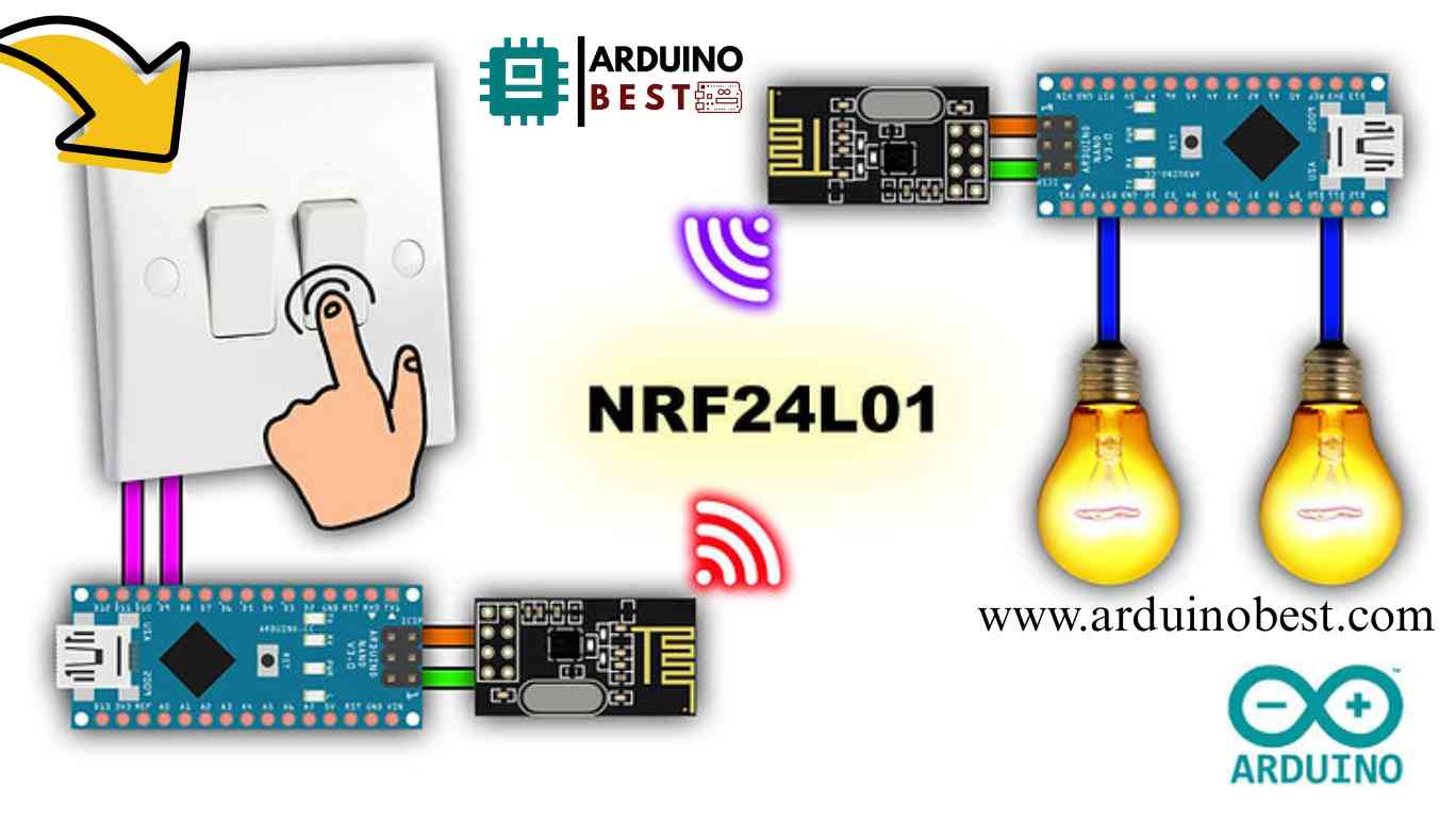
Home automation is transforming the way we interact with everyday appliances. Using an Arduino with an NRF24L01 transceiver, we can create a wireless relay system to control lights remotely. This project is perfect for beginners and enthusiasts looking to explore wireless communication and relay automation.
With a few affordable components, you can build a reliable wireless relay switch for controlling lights or other electronic devices. In this guide, we will cover the necessary components, circuit design, coding, troubleshooting, and practical applications.
Learn more about Arduino and wireless communication here.
Understanding the Components
To build this project, you need the following:
1. Arduino Microcontroller
- Any Arduino board (e.g., Arduino Uno, Nano, Mega)
- Handles logic and communication between components
2. NRF24L01 Transceiver Module
- Operates at 2.4GHz frequency
- Supports low-power, long-range wireless communication
- Variants available with PA/LNA for extended range
Read more about NRF24L01 transceivers and their applications.
3. Relay Module
- Controls high-voltage AC or DC devices
- Can switch lights, fans, or other appliances
4. Power Supply Considerations
- NRF24L01 requires a dedicated 3.3V regulator for stable operation
- Ensure Arduino and relay have adequate power supply
Circuit Design and Wiring
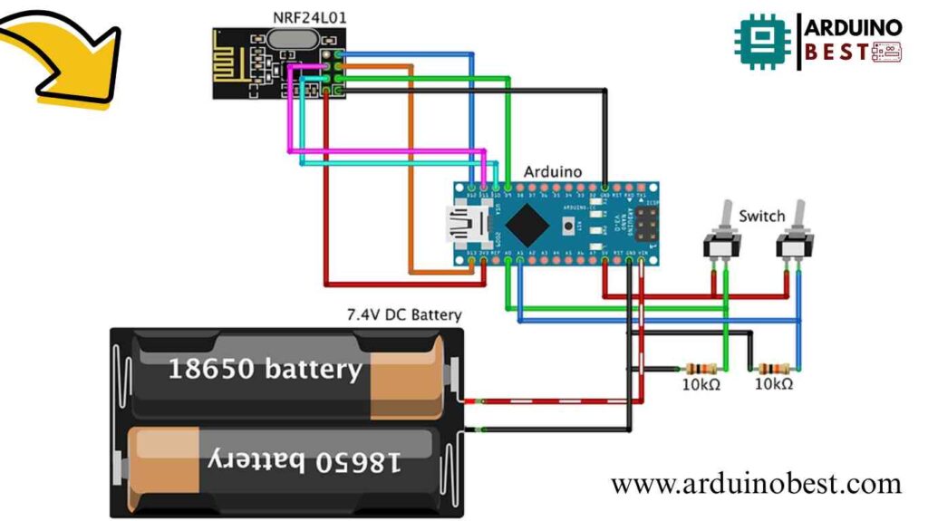
Transmitter Setup

- Connect push button to Arduino for switching the light
- Interface NRF24L01 to Arduino using SPI pins
- Ensure proper power management for the module
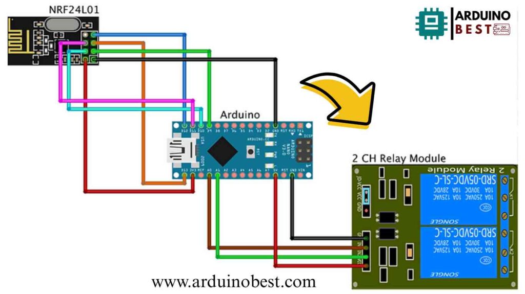
Receiver Setup

- Connect NRF24L01 to the receiver Arduino
- Interface relay module to control the light
- Ensure optocoupler isolation for high-voltage safety
Schematic Diagram
- Provide detailed wiring diagrams
- Highlight essential connections for easy debugging
Programming the Arduino
Installing Required Libraries
- Install
RF24andSPIlibraries in Arduino IDE - Include necessary header files in the sketch
Transmitter Code
- Initialize NRF24L01 module
- Read push button state
- Send wireless signals to the receiver
#include <SPI.h>
#include <nRF24L01.h>
#include <RF24.h>

#define buttonPin1 A0
#define buttonPin2 A1

int buttonState1 = 0;
int buttonState2 = 0;

RF24 radio(9, 10); // CE, CSN

const byte address[6] = "00002";

void setup() {
  pinMode(buttonPin1, INPUT);
  pinMode(buttonPin2, INPUT);
  Serial.begin(9600);
  radio.begin();
  radio.openWritingPipe(address);
  radio.setPALevel(RF24_PA_MIN);
  radio.stopListening();
}
void loop() {
  buttonState1 = digitalRead(buttonPin1);
  buttonState2 = digitalRead(buttonPin2);

  if (buttonState1 == 1)
  {
    buttonState1 = 1;
  }
  else  if (buttonState1 == 0)
  {
    buttonState1 = 0;
  }
  if (buttonState2 == 1)
  {
    buttonState2 = 3;
  }
  else  if (buttonState2 == 0)
  {
    buttonState2 = 2;
  }
  Serial.print(buttonState1);
  Serial.print("\t");
  Serial.println(buttonState2);
  radio.write(&buttonState1, sizeof(buttonState1));
  radio.write(&buttonState2, sizeof(buttonState2));
}
Receiver Code
- Initialize NRF24L01 module
- Receive wireless signals
- Activate relay module to control the light
#include <SPI.h>
#include <nRF24L01.h>
#include <RF24.h>

#define relayPin1 A0
#define relayPin2 A1

int buttonState = 0;

RF24 radio(9, 10); // CE, CSN
const byte address[6] = "00002";

void setup() {
  Serial.begin(9600);
  pinMode(relayPin1, OUTPUT);
  pinMode(relayPin2, OUTPUT);
  digitalWrite(relayPin1, LOW);
  digitalWrite(relayPin2, LOW);
  radio.begin();
  radio.openReadingPipe(0, address);
  radio.setPALevel(RF24_PA_MIN);
}

void loop() {
  radio.startListening();
  while (!radio.available());
  radio.read(&buttonState, sizeof(buttonState));
  Serial.println(buttonState);

  if (buttonState == 1) {
    digitalWrite(relayPin1, HIGH);
  }
  else  if (buttonState == 0) {
    digitalWrite(relayPin1, LOW);
  }
  else if (buttonState == 3) {
    digitalWrite(relayPin2, HIGH);
  }
  else  if (buttonState == 2) {
    digitalWrite(relayPin2, LOW);
  }
}
Code Optimization
- Implement error handling
- Use acknowledgment packets for reliable communication
- Optimize power consumption for battery-powered projects
Testing and Troubleshooting
Initial Testing
- Verify connections using serial print statements
- Check if NRF24L01 modules communicate properly
Common Issues and Fixes
- No communication between modules? Check wiring and power supply.
- Relay not switching? Verify relay module wiring and Arduino pin configurations.
- Short range? Use PA/LNA module and an external antenna.
Applications and Future Enhancements
Practical Applications
- Home automation
- Remote light control
- Industrial equipment management
Future Enhancements
- Use multiple relays for controlling multiple devices
- Integrate with IoT platforms for smartphone control
- Add sensor-based automation for smart lighting
FAQs
How do I increase the range of NRF24L01?
Use a module with PA/LNA and an external antenna.
Can I control multiple relays with a single transmitter?
Yes, by assigning unique addresses to multiple receivers.
What precautions should I take with high-voltage devices?
Use optocouplers and proper insulation to avoid electrical hazards.
How can I ensure secure communication?
Use encryption techniques and unique RF addresses.
Are there alternative wireless modules?
Yes, you can use ESP8266, Bluetooth modules, or LoRa for different use cases.
Conclusion
This project provides an efficient way to control lights remotely using an Arduino NRF24L01 transceiver-controlled relay. With proper setup and optimization, it can be expanded into a full-fledged home automation system. Experiment with additional features and explore new possibilities for wireless control in automation projects.
Here we suggest other Arduino Projects:
1- Complete Guide for DHT11/DHT22 Humidity and Temperature Sensor With Arduino
2- DHT11 – Temperature and Humidity Sensor
3- DHT22 – Temperature and Humidity Sensor (more accurate than DHT11)
4- BMP180 – Barometric Pressure and Altitude Sensor
5- BMP280 – Barometric Pressure & Temperature Sensor
6- BME280 – Temperature, Humidity, and Pressure Sensor
7- Arduino Flex Sensor Controlled Robot Hand
8- Arduino ECG Heart Rate Monitor AD8232 Demo
9- Arduino NRF24L01 Wireless Joystick Robot Car10- Arduino Force Sensor Anti-Theft Alarm System

