
Table of Contents
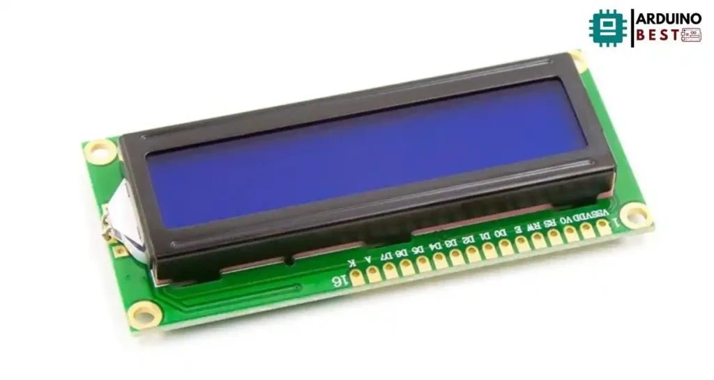
The 16×2 LCD module is one of the most popular display devices used in electronics projects. Whether you are working on a simple Arduino project or building a complex embedded system, a 16×2 character LCD provides a low-cost and straightforward way to add a user interface.
In this detailed guide, you will learn everything about the 16×2 LCD module, from its pin configuration and specifications to interfacing methods and troubleshooting tips. By the end of this article, you will be able to integrate a 16×2 LCD into any project confidently.
Introduction to 16×2 LCD Modules
A 16×2 LCD module is a character display capable of showing 16 characters per line over 2 lines. Each character is displayed in a 5×8 pixel matrix. These modules are widely used because of their affordability, low power consumption, and simplicity.
They are especially popular in:
- DIY electronics
- Embedded systems
- Industrial control panels
- Consumer electronics
For example, many Arduino tutorials such as the Arduino LCD Display Tutorial showcase how beginner-friendly and versatile the 16×2 LCD module can be.
Understanding the 16×2 LCD Module
The 16×2 character LCD can display a wide range of ASCII characters and even user-defined custom symbols. The compact size and 2-line display make it ideal for most applications where full graphic displays are unnecessary.
Some key points:
- 16 characters across each line
- 2 rows for more information
- 5×8 pixel structure for each character
- Contrast adjustable via a potentiometer
Different sizes like 8×2 LCDs and 20×4 LCDs exist, but the 16×2 remains the most balanced between information display and board space.
For an even deeper dive into connecting and understanding the module, the Grove 16×2 LCD Module Information is an excellent resource.
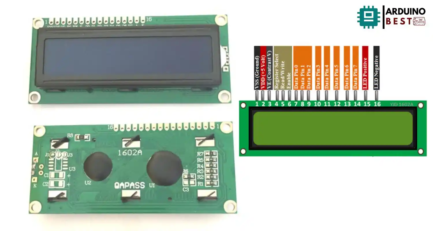
Pin Configuration and Functions
The 16×2 LCD module has a 16-pin configuration that supports either 4-bit or 8-bit communication modes. Here’s a breakdown of the pins:
- VSS – Ground
- VDD – Power Supply (+5V)
- V0 – Contrast Adjustment
- RS (Register Select) – Command or data register selector
- RW (Read/Write) – Selects Read or Write operation
- E (Enable) – Latches data
- D0 to D7 – Data lines
- A (Anode) – LED backlight positive
- K (Cathode) – LED backlight ground
Operating the LCD in 4-bit mode reduces the number of data lines required, making it ideal for microcontrollers with limited GPIO availability.
Technical Specifications
When selecting or using a 16×2 LCD, knowing the technical specs is crucial for optimal performance:
- Operating Voltage: 4.7V–5.3V
- Backlight: Optional, usually white, green, or blue
- Character Size: Approx. 5.55mm × 8.00mm
- Operating Temperature: 0°C to 50°C
- Storage Temperature: -10°C to 60°C
Some displays offer multi-color backlights, and more robust versions can operate in harsher conditions.
Controller IC: HD44780
At the heart of almost every 16×2 LCD is the HD44780 controller, developed by Hitachi. This IC standardizes the command set and communication protocol, allowing easy integration across platforms.
Features of the HD44780:
- Supports 4-bit and 8-bit data interfaces
- Includes a CGRAM for custom characters
- Offers cursor movement, display shift, and blinking effects
You can explore the original HD44780 LCD Controller Datasheet for an in-depth understanding of command codes and initialization sequences.
Interfacing with Microcontrollers
Connecting to Arduino
The Arduino ecosystem provides one of the simplest ways to interface a 16×2 LCD. Typically, you use the LiquidCrystal library.
Key steps:
- Wire the LCD’s RS, E, D4–D7 pins to Arduino digital pins
- Connect power, ground, and a potentiometer for contrast
- Initialize the LCD with
LiquidCrystal(rs, enable, d4, d5, d6, d7); - Use
lcd.begin(16, 2);to start the display - Use
lcd.print("Hello, World!");to display text
Using I2C with Arduino
You can add an I2C adapter to reduce pin usage to just two wires (SDA and SCL).
Advantages:
- Fewer wires
- Simplified coding
- Ability to chain multiple I2C devices
Connecting to Raspberry Pi
Using a 16×2 LCD with the Raspberry Pi requires connecting the data pins to GPIOs and using libraries like RPLCD in Python.
Steps include:
- Wiring according to 4-bit mode
- Installing the library with
pip install RPLCD - Coding simple scripts to display messages
The Raspberry Pi LCD Display Guide provides excellent beginner instructions for setting up the 16×2 LCD on a Raspberry Pi.
Communication Interfaces
While most basic setups use parallel communication, advanced users prefer I2C or SPI methods.
- Parallel (4-bit/8-bit): Direct data transfer; faster but uses more pins
- I2C (Serial): Only two wires needed; slower but efficient
- SPI (Serial): Faster serial communication, suitable for high-speed applications
Choosing between these depends on your project’s requirements for speed, wiring complexity, and available GPIOs.
Practical Applications
The 16×2 LCD module finds real-world applications across numerous fields:
- DIY Arduino clocks and counters
- Home automation displays
- Industrial machine status monitors
- Robotics sensor readings
- Educational STEM kits for students
Its versatility, reliability, and simplicity make it an unbeatable option for prototyping and learning.
Troubleshooting and Tips
Encountering problems when using a 16×2 LCD is common, but most issues are easily fixable:
- Blank Screen: Adjust the contrast using a potentiometer
- Garbled Characters: Ensure proper initialization in the code
- No Display: Check all wiring and supply voltage
- Backlight Off: Verify the connection of LED+ and LED- pins
For I2C LCD modules, double-check the device address, often found via an I2C scanner sketch.
FAQs
What is a 16×2 LCD module?
A 16×2 LCD module is a display device that shows up to 16 characters per line over 2 rows using a 5×8 pixel character matrix.
How do I connect a 16×2 LCD to an Arduino?
You connect it by wiring the LCD’s control and data pins to Arduino’s digital pins, using a potentiometer to control contrast, and coding with the LiquidCrystal library.
What is the difference between 4-bit and 8-bit modes?
- 4-bit Mode: Only 4 data lines used; slower but saves GPIOs
- 8-bit Mode: All 8 data lines used; faster but requires more pins
Can I use a 16×2 LCD with a Raspberry Pi?
Yes, by connecting the LCD to the Raspberry Pi’s GPIO pins and using libraries like RPLCD for programming.
How do I create custom characters on a 16×2 LCD?
You can define custom characters using the LCD’s CGRAM (Character Generator RAM) by uploading a binary array that maps pixels.
What is the function of the HD44780 controller?
It manages the internal operations of the LCD, including character rendering, cursor movement, and communication protocols.
How do I adjust the contrast on my LCD?
Attach a 10K potentiometer to the V0 pin. Rotate the knob to increase or decrease the contrast.
Why is my LCD not displaying any characters?
Possible reasons include incorrect wiring, missing initialization code, incorrect voltage levels, or contrast settings being too low.
Conclusion
The 16×2 LCD module remains a top choice for adding visual feedback to electronic projects. With a straightforward interface, customizable characters, and reliable performance, it is perfect for both beginners and seasoned engineers.
By understanding its pinout, wiring methods, controller IC, and troubleshooting basics, you can unlock countless project possibilities with the 16×2 LCD module.