
Table of Contents
Introduction
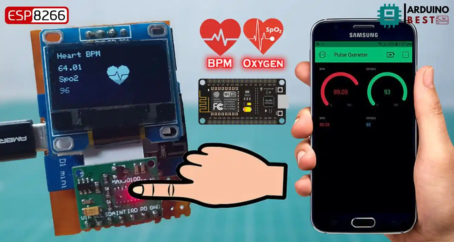
In today’s world, health monitoring is becoming increasingly important, especially for those with pre-existing conditions or fitness enthusiasts. The pulse oximeter is a vital tool used to measure SpO₂ (blood oxygen saturation) and BPM (beats per minute), helping individuals keep track of their respiratory and cardiovascular health. With the integration of modern technology, projects like the ESP8266 Pulse Oximeter Blynk BPM SpO2 offer a seamless and cost-effective solution for continuous monitoring.
The project uses an ESP8266 microcontroller, a MAX30100 pulse oximeter sensor, and the Blynk app to provide real-time SpO₂ and BPM readings. The system allows users to remotely monitor their health metrics via a smartphone app, which is ideal for home health management or fitness tracking. By combining the powerful ESP8266 with IoT (Internet of Things) capabilities, this project offers a practical solution for those looking to monitor their health data easily.
To dive deeper into IoT development, you may find resources like How IoT is Transforming Health Monitoring useful for understanding the broader context of integrating IoT into health systems.
Understanding Pulse Oximetry and Heart Rate Monitoring
Before we dive into building the system, let’s first explore the significance of pulse oximetry and heart rate monitoring.
What is Pulse Oximetry?
Pulse oximetry is a non-invasive method used to measure the oxygen saturation in a person’s blood. The device works by emitting light through a body part, usually a fingertip, and detecting how much light passes through. This helps determine the amount of oxygen being carried in the bloodstream. Maintaining a healthy oxygen level is crucial, as low SpO₂ levels can indicate underlying respiratory problems or other health issues.
- Normal SpO₂ levels typically range from 95% to 100%.
- Levels below 90% indicate hypoxemia, a condition that requires medical attention.
Heart Rate Monitoring (BPM)
The BPM (beats per minute) refers to the number of heartbeats in a minute. Monitoring BPM is important for understanding the cardiovascular health of an individual. A normal heart rate for adults is usually between 60 and 100 beats per minute, depending on factors such as age, physical activity, and overall health.
- Resting heart rate measurements can help detect irregularities.
- Tracking BPM can help improve physical fitness and alert to potential health issues.
By integrating these two parameters into a simple system, you gain a powerful tool for ongoing health monitoring. For more insights on cardiovascular health, check out American Heart Association’s Guide to Monitoring Heart Rate.
Components Required
Building the ESP8266 pulse oximeter Blynk BPM SpO2 system requires the following components:
Hardware Components
- NodeMCU ESP8266: This microcontroller enables Wi-Fi connectivity for sending data to the Blynk app.
- MAX30100 Pulse Oximeter Sensor: Measures SpO₂ and BPM levels using infrared light.
- 0.96″ OLED Display: Displays real-time readings of SpO₂ and BPM.
- Jumper Wires and Breadboard: For wiring the components together.
Software Components
- Arduino IDE: Used to program the ESP8266.
- Blynk App: A mobile app for controlling and monitoring IoT devices.
- Libraries: Use Wire.h, MAX30100_PulseOximeter.h, and BlynkSimpleEsp8266.h to facilitate communication between hardware and the Blynk app.
These components combine to create an efficient and easy-to-build health monitoring system. You can find useful tips on getting started with the ESP8266 and IoT apps on platforms like Espressif Systems’ official resources.
Wiring and Circuit Design
Proper wiring of the components is critical for ensuring the system works as expected. Here is a step-by-step guide to the wiring:
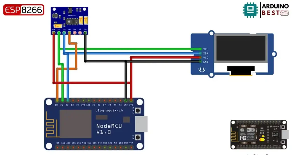
Connecting the MAX30100 to ESP8266
- VCC to 3.3V
- GND to GND
- SCL to D1
- SDA to D2
- INT to D0
Integrating the OLED Display
- Connect the SCL and SDA pins of the OLED display to the ESP8266‘s D1 and D2 pins, respectively.
- If needed, adjust the I2C address for proper communication.
Power Considerations
- Ensure a stable 3.3V power supply for both the ESP8266 and the MAX30100 sensor.
These steps ensure that all components are correctly wired, enabling smooth data transmission to the Blynk app. For further assistance, check out this detailed guide on connecting ESP8266 with sensors.
Setting Up the Blynk App
The Blynk app is essential for viewing and interacting with the health data from the ESP8266 Pulse Oximeter. Here’s how to set it up:
Creating a Blynk Project
- Open the Blynk app and create a new project.
- Select the ESP8266 device and choose the connection type (Wi-Fi).
- Blynk will provide an authentication token, which must be included in the code.
Adding Widgets
- Add Value Display widgets to monitor SpO₂ and BPM.
- Assign virtual pins (e.g., V7 for BPM, V8 for SpO₂) for displaying the values.
Configuring the Dashboard
- Customize the layout by arranging the widgets to display relevant information.
- Set up notifications to receive alerts for abnormal readings.
These steps are crucial for ensuring seamless communication between the ESP8266 and the Blynk app. For detailed Blynk tutorials, refer to the Blynk Documentation.
Programming the ESP8266
To program the ESP8266 microcontroller, follow these steps:
#include <Wire.h>
#include "MAX30100_PulseOximeter.h"
#define BLYNK_PRINT Serial
#include <Blynk.h>
#include <ESP8266WiFi.h>
#include <BlynkSimpleEsp8266.h>

#include "Wire.h"
#include "Adafruit_GFX.h"
#include "OakOLED.h"

#define REPORTING_PERIOD_MS 1000
OakOLED oled;

char auth[] = "--------------------";             // Authentication Token Sent by Blynk
char ssid[] = "--------";        //WiFi SSID
char pass[] = "--------";        //WiFi Password

// Connections : SCL PIN - D1 , SDA PIN - D2 , INT PIN - D0
PulseOximeter pox;

float BPM, SpO2;
uint32_t tsLastReport = 0;

const unsigned char bitmap [] PROGMEM=
{
0x00, 0x00, 0x00, 0x00, 0x01, 0x80, 0x18, 0x00, 0x0f, 0xe0, 0x7f, 0x00, 0x3f, 0xf9, 0xff, 0xc0,
0x7f, 0xf9, 0xff, 0xc0, 0x7f, 0xff, 0xff, 0xe0, 0x7f, 0xff, 0xff, 0xe0, 0xff, 0xff, 0xff, 0xf0,
0xff, 0xf7, 0xff, 0xf0, 0xff, 0xe7, 0xff, 0xf0, 0xff, 0xe7, 0xff, 0xf0, 0x7f, 0xdb, 0xff, 0xe0,
0x7f, 0x9b, 0xff, 0xe0, 0x00, 0x3b, 0xc0, 0x00, 0x3f, 0xf9, 0x9f, 0xc0, 0x3f, 0xfd, 0xbf, 0xc0,
0x1f, 0xfd, 0xbf, 0x80, 0x0f, 0xfd, 0x7f, 0x00, 0x07, 0xfe, 0x7e, 0x00, 0x03, 0xfe, 0xfc, 0x00,
0x01, 0xff, 0xf8, 0x00, 0x00, 0xff, 0xf0, 0x00, 0x00, 0x7f, 0xe0, 0x00, 0x00, 0x3f, 0xc0, 0x00,
0x00, 0x0f, 0x00, 0x00, 0x00, 0x06, 0x00, 0x00, 0x00, 0x00, 0x00, 0x00, 0x00, 0x00, 0x00, 0x00
};

void onBeatDetected()
{
    Serial.println("Beat Detected!");
    oled.drawBitmap( 60, 20, bitmap, 28, 28, 1);
    oled.display();
}

void setup()
{
    Serial.begin(115200);
    oled.begin();
    oled.clearDisplay();
    oled.setTextSize(1);
    oled.setTextColor(1);
    oled.setCursor(0, 0);

    oled.println("Initializing pulse oximeter..");
    oled.display();

    pinMode(16, OUTPUT);
    Blynk.begin(auth, ssid, pass);

    Serial.print("Initializing Pulse Oximeter..");

    if (!pox.begin())
    {
         Serial.println("FAILED");
         oled.clearDisplay();
         oled.setTextSize(1);
         oled.setTextColor(1);
         oled.setCursor(0, 0);
         oled.println("FAILED");
         oled.display();
         for(;;);
    }
    else
    {
         oled.clearDisplay();
         oled.setTextSize(1);
         oled.setTextColor(1);
         oled.setCursor(0, 0);
         oled.println("SUCCESS");
         oled.display();
         Serial.println("SUCCESS");
         pox.setOnBeatDetectedCallback(onBeatDetected);
    }

    // The default current for the IR LED is 50mA and it could be changed by uncommenting the following line.
     //pox.setIRLedCurrent(MAX30100_LED_CURR_7_6MA);

}

void loop()
{
    pox.update();
    Blynk.run();

    BPM = pox.getHeartRate();
    SpO2 = pox.getSpO2();
    if (millis() - tsLastReport > REPORTING_PERIOD_MS)
    {
        Serial.print("Heart rate:");
        Serial.print(BPM);
        Serial.print(" SpO2:");
        Serial.print(SpO2);
        Serial.println(" %");

        Blynk.virtualWrite(V7, BPM);
        Blynk.virtualWrite(V8, SpO2);

        oled.clearDisplay();
        oled.setTextSize(1);
        oled.setTextColor(1);
        oled.setCursor(0,16);
        oled.println(pox.getHeartRate());

        oled.setTextSize(1);
        oled.setTextColor(1);
        oled.setCursor(0, 0);
        oled.println("Heart BPM");

        oled.setTextSize(1);
        oled.setTextColor(1);
        oled.setCursor(0, 30);
        oled.println("Spo2");

        oled.setTextSize(1);
        oled.setTextColor(1);
        oled.setCursor(0,45);
        oled.println(pox.getSpO2());
        oled.display();

        tsLastReport = millis();
    }
}
Setting Up the Arduino IDE
- Install the necessary board definitions and libraries in the Arduino IDE.
- Select the ESP8266 board from the Tools menu and set the correct port.
Writing the Code
The code is essential for reading data from the sensor and sending it to the Blynk app. Here’s a basic overview of the program:
- Initialize the Blynk connection using the authentication token.
- Set up the MAX30100 sensor to measure SpO₂ and BPM.
- Use the
virtualWrite()function to send data to the Blynk app. - Implement error handling for situations where the sensor fails to provide data.
Handling Sensor Data
- Ensure that the sensor’s data transmission intervals are optimized.
- Error handling is essential to avoid issues with inconsistent sensor readings.
Testing and Calibration
After assembling and programming your system, it’s time to test it:
Initial Testing
- Power up the system and check the OLED display for readings.
- Verify that the data is properly transmitted to the Blynk app.
Calibrating the Sensor
- Compare the readings from your ESP8266 Pulse Oximeter with a clinically accurate device.
- Adjust the code or hardware if necessary for more accurate results.
Troubleshooting Common Issues
- If the Blynk app is not showing data, check the wiring and code for errors.
- Ensure that the sensor is properly initialized and that the ESP8266 is connected to Wi-Fi.
Applications and Use Cases
The ESP8266 Pulse Oximeter Blynk BPM SpO2 system has various applications:
- Home Health Monitoring: Track SpO₂ and BPM at home, ensuring your health is always in check.
- Fitness Tracking: Monitor heart rate during workouts for better fitness planning.
- Remote Patient Monitoring: Share data with healthcare providers for continuous monitoring.
- Educational Projects: Use the system for learning about IoT, health monitoring, and microcontrollers.
For more on the impact of IoT in healthcare, see this article on IoT’s Role in Remote Health Monitoring.
Advanced Enhancements
For those looking to expand their projects, here are some advanced features you can add:
- Integrating Other Sensors: Add temperature or humidity sensors for more comprehensive health tracking.
- Using ESP32: For more powerful features, upgrade to the ESP32 microcontroller.
- Data Logging and Analysis: Log your health data to cloud platforms like Google Sheets or ThingSpeak.
- Creating a Standalone Device: Design a custom PCB and package the system into a compact device.
FAQs
What is the maximum distance the ESP8266 can transmit data?
The ESP8266 can transmit data over a Wi-Fi range of approximately 100 meters in open space, depending on the environment and obstacles.
Can I use this system for real-time monitoring of patients?
Yes, you can use the system to monitor health data in real-time, and by integrating it with cloud services, you can even share the data with healthcare providers for remote monitoring.
How do I calibrate the MAX30100 sensor?
Calibration involves comparing the readings of your device with a clinically approved pulse oximeter and adjusting the code or sensor placement for accurate results.
This comprehensive guide provides a step-by-step approach to building and utilizing an ESP8266 Pulse Oximeter Blynk BPM SpO2 system, enabling you to monitor your health efficiently.
Conclusion
The ESP8266 Pulse Oximeter Blynk BPM SpO2 project is an innovative and affordable solution for monitoring vital health metrics such as blood oxygen saturation and heart rate. By combining the ESP8266 microcontroller with the MAX30100 sensor and the Blynk app, users can easily track their health in real-time through a mobile interface. This system is not only perfect for home healthcare but also ideal for fitness enthusiasts and remote patient monitoring.
With simple components, clear wiring instructions, and a user-friendly app interface, this project opens the door to creating personalized health monitoring systems. Additionally, the potential for future enhancements—such as integrating more sensors or logging data to cloud services—makes this setup highly adaptable for various health-related applications.
As the demand for home health monitoring solutions continues to grow, the ESP8266 Pulse Oximeter Blynk BPM SpO2 serves as a great starting point for anyone looking to explore the intersection of IoT and health technology. With this project, you’re not just building a device; you’re contributing to a healthier, more connected world.
Projects ESP8266 nodemcu
1- ESP8266 NodeMCU: A Comprehensive Guide to IoT Development
2- Control LED with ESP8266 NodeMCU: A Beginner’s Guide
3- Integrating a Joystick with ESP8266 NodeMCU: A Comprehensive Guide
4- esp8266 nodemcu with Flame Sensor
5- ESP8266 NodeMCU with Heartbeat Sensor
6- ESP8266 NodeMCU with KY-027 Magic Cup Light
7- ESP8266 NodeMCU with Hall Magnetic Sensor
8- ESP8266 NodeMCU with relay module 5v
9- ESP8266 NodeMCU with Linear Hall Sensor