
Table of Contents
Introduction
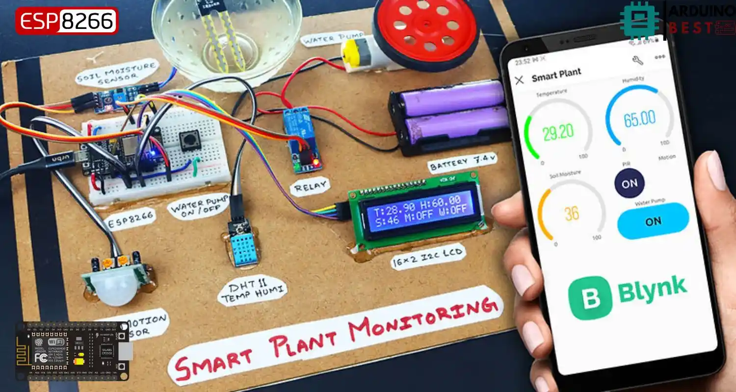
In the modern era of technology-driven solutions, plant care has been revolutionized through the use of smart plant monitoring systems. These systems leverage IoT (Internet of Things) technology to automate, monitor, and manage plant health from anywhere. One of the most accessible and efficient combinations for such projects is the ESP8266 microcontroller paired with the Blynk IoT platform. This setup provides users with a user-friendly, scalable, and highly customizable solution to maintain their garden or indoor plants efficiently.
This guide will walk you through building a comprehensive ESP8266 Blynk IoT Smart Plant Monitoring System, highlighting the essential components, setup process, programming, and enhancements.
Understanding the Core Components
ESP8266 Microcontroller
- Low-cost Wi-Fi enabled microcontroller
- Ideal for small-scale and DIY IoT projects
- Supports integration with various sensors
Blynk IoT Platform
- A powerful app-based interface for managing IoT devices
- Easily connects to ESP8266 for real-time data visualization
- Learn more at Explore Blynk’s IoT Platform
Sensors and Actuators
- Soil moisture sensor: Detects the water content in soil
- DHT11/DHT22 sensor: Measures temperature and humidity
- Relay module: Automates devices like water pumps
- Water pump: Controls irrigation based on sensor input
Setting Up the Hardware
Required Components
- ESP8266 NodeMCU
- Soil moisture sensor
- DHT11/DHT22 sensor
- Relay module
- Water pump
- Jumper wires and breadboard
- Power supply or battery pack
Circuit Diagram and Connections
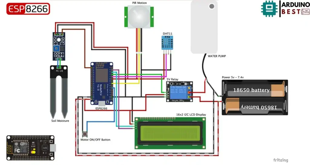
- Connect the sensors to the analog/digital pins of ESP8266
- Use the relay to connect the water pump
- Ensure correct voltage and ground connections to avoid damage
Power Supply Considerations
- Use a 5V battery pack or USB adapter
- Consider solar-powered options for outdoor setups
Configuring the Blynk Application
Creating a Blynk Account and Project
- Register on the Blynk app and create a new project
- Choose ESP8266 as the device and Wi-Fi as the connection type
Setting Up Virtual Pins and Widgets
- Assign sensors to virtual pins in the Blynk app
- Add widgets like gauges, displays, and buttons
- Refer to the ESP8266 Documentation for connection details
Integrating with ESP8266
- Generate an authentication token from Blynk
- Use the Arduino IDE to upload code to ESP8266
- Establish connection using Blynk and Wi-Fi credentials
Developing the Firmware
Programming the ESP8266
- Install the ESP8266 board package in Arduino IDE
- Include required libraries:
ESP8266WiFi,BlynkSimpleEsp8266,DHT, etc.
//Include the library files
#include <LiquidCrystal_I2C.h>
#define BLYNK_PRINT Serial
#include <ESP8266WiFi.h>
#include <BlynkSimpleEsp8266.h>
#include <DHT.h>

//Initialize the LCD display
LiquidCrystal_I2C lcd(0x3F, 16, 2);


char auth[] = "     ";  //Enter your Blynk Auth token
char ssid[] = "     ";  //Enter your WIFI SSID
char pass[] = "     ";  //Enter your WIFI Password

DHT dht(D4, DHT11);//(DHT sensor pin,sensor type)  D4 DHT11 Temperature Sensor
BlynkTimer timer;

//Define component pins
#define soil A0     //A0 Soil Moisture Sensor
#define PIR D5      //D5 PIR Motion Sensor
int PIR_ToggleValue;

void checkPhysicalButton();
int relay1State = LOW;
int pushButton1State = HIGH;
#define RELAY_PIN_1       D3   //D3 Relay
#define PUSH_BUTTON_1     D7   //D7 Button
#define VPIN_BUTTON_1    V12

//Create three variables for pressure
double T, P;
char status;


void setup() {
  Serial.begin(9600);
  lcd.begin();
  lcd.backlight();
  pinMode(PIR, INPUT);

 pinMode(RELAY_PIN_1, OUTPUT);
 digitalWrite(RELAY_PIN_1, LOW);
  pinMode(PUSH_BUTTON_1, INPUT_PULLUP);
  digitalWrite(RELAY_PIN_1, relay1State);


  Blynk.begin(auth, ssid, pass, "blynk.cloud", 80);
  dht.begin();

  lcd.setCursor(0, 0);
  lcd.print("  Initializing  ");
  for (int a = 5; a <= 10; a++) {
    lcd.setCursor(a, 1);
    lcd.print(".");
    delay(500);
  }
  lcd.clear();
  lcd.setCursor(11, 1);
  lcd.print("W:OFF");
  //Call the function
  timer.setInterval(100L, soilMoistureSensor);
  timer.setInterval(100L, DHT11sensor);
  timer.setInterval(500L, checkPhysicalButton);
}


//Get the DHT11 sensor values
void DHT11sensor() {
  float h = dht.readHumidity();
  float t = dht.readTemperature();

  if (isnan(h) || isnan(t)) {
    Serial.println("Failed to read from DHT sensor!");
    return;
  }
  Blynk.virtualWrite(V0, t);
  Blynk.virtualWrite(V1, h);

  lcd.setCursor(0, 0);
  lcd.print("T:");
  lcd.print(t);

  lcd.setCursor(8, 0);
  lcd.print("H:");
  lcd.print(h);

}


//Get the soil moisture values
void soilMoistureSensor() {
  int value = analogRead(soil);
  value = map(value, 0, 1024, 0, 100);
  value = (value - 100) * -1;

  Blynk.virtualWrite(V3, value);
  lcd.setCursor(0, 1);
  lcd.print("S:");
  lcd.print(value);
  lcd.print(" ");

}

//Get the PIR sensor values
void PIRsensor() {
  bool value = digitalRead(PIR);
  if (value) {
    Blynk.logEvent("pirmotion","WARNNG! Motion Detected!"); //Enter your Event Name
    WidgetLED LED(V5);
    LED.on();
  } else {
    WidgetLED LED(V5);
    LED.off();
  }
  }

BLYNK_WRITE(V6)
{
 PIR_ToggleValue = param.asInt();
}


BLYNK_CONNECTED() {
  // Request the latest state from the server
  Blynk.syncVirtual(VPIN_BUTTON_1);
}

BLYNK_WRITE(VPIN_BUTTON_1) {
  relay1State = param.asInt();
  digitalWrite(RELAY_PIN_1, relay1State);
}

void checkPhysicalButton()
{
  if (digitalRead(PUSH_BUTTON_1) == LOW) {
    // pushButton1State is used to avoid sequential toggles
    if (pushButton1State != LOW) {

      // Toggle Relay state
      relay1State = !relay1State;
      digitalWrite(RELAY_PIN_1, relay1State);

      // Update Button Widget
      Blynk.virtualWrite(VPIN_BUTTON_1, relay1State);
    }
    pushButton1State = LOW;
  } else {
    pushButton1State = HIGH;
  }
}


void loop() {
    if (PIR_ToggleValue == 1)
    {
    lcd.setCursor(5, 1);
    lcd.print("M:ON ");
      PIRsensor();
      }
     else
     {
    lcd.setCursor(5, 1);
    lcd.print("M:OFF");
    WidgetLED LED(V5);
    LED.off();
     }

if (relay1State == HIGH)
{
  lcd.setCursor(11, 1);
  lcd.print("W:ON ");
  }
  else if (relay1State == LOW)
  {
    lcd.setCursor(11, 1);
    lcd.print("W:OFF");
    }


  Blynk.run();//Run the Blynk library
  timer.run();//Run the Blynk timer

  }
Sensor Data Acquisition
- Read data from soil and environmental sensors
- Format and send the data to Blynk using virtual pins
Automating Plant Care
- Define moisture thresholds in code
- Automatically activate the relay to water the plant
Enhancing the System
Adding More Sensors
- Integrate light sensors, pH sensors for comprehensive monitoring
- Expand the number of plants monitored with more sensors and pins
Implementing Notifications
- Use Blynk to send alerts on low moisture or high temperature
Data Logging and Analysis
- Store historical data using cloud platforms
- Analyze trends to optimize watering schedules
Troubleshooting Common Issues
Connectivity Problems
- Ensure strong Wi-Fi signal
- Verify correct credentials in code
Sensor Calibration
- Test sensors independently for accurate readings
- Calibrate using known reference values
Power Management
- Use voltage regulators for stable power
- Monitor battery levels with voltage sensors
FAQs
How do I calibrate the soil moisture sensor? Dry and wet calibrations with known water levels help set accurate thresholds.
Can I use other microcontrollers instead of ESP8266? Yes, boards like ESP32 or Arduino with Wi-Fi shields can be used.
How secure is the Blynk platform? Blynk uses secure cloud communications; however, always update credentials and firmware.
What is the range of Wi-Fi connectivity for ESP8266? Typically 30-50 meters indoors, depending on obstacles and router strength.
Can I control multiple plants with one system? Yes, you can use multiple sensors and expand the code accordingly.
Conclusion
The ESP8266 Blynk IoT Smart Plant Monitoring System offers a cost-effective and scalable way to automate and monitor plant care. With simple hardware and powerful app integration, it empowers users to ensure optimal plant health while saving time and effort. Expand and enhance your system to fit your gardening needs.
Projects ESP8266 nodemcu
1- ESP8266 NodeMCU: A Comprehensive Guide to IoT Development
2- Control LED with ESP8266 NodeMCU: A Beginner’s Guide
3- Integrating a Joystick with ESP8266 NodeMCU: A Comprehensive Guide
4- esp8266 nodemcu with Flame Sensor
5- ESP8266 NodeMCU with Heartbeat Sensor
6- ESP8266 NodeMCU with KY-027 Magic Cup Light
7- ESP8266 NodeMCU with Hall Magnetic Sensor
8- ESP8266 NodeMCU with relay module 5v
9- ESP8266 NodeMCU with Linear Hall Sensor