
Table of Contents
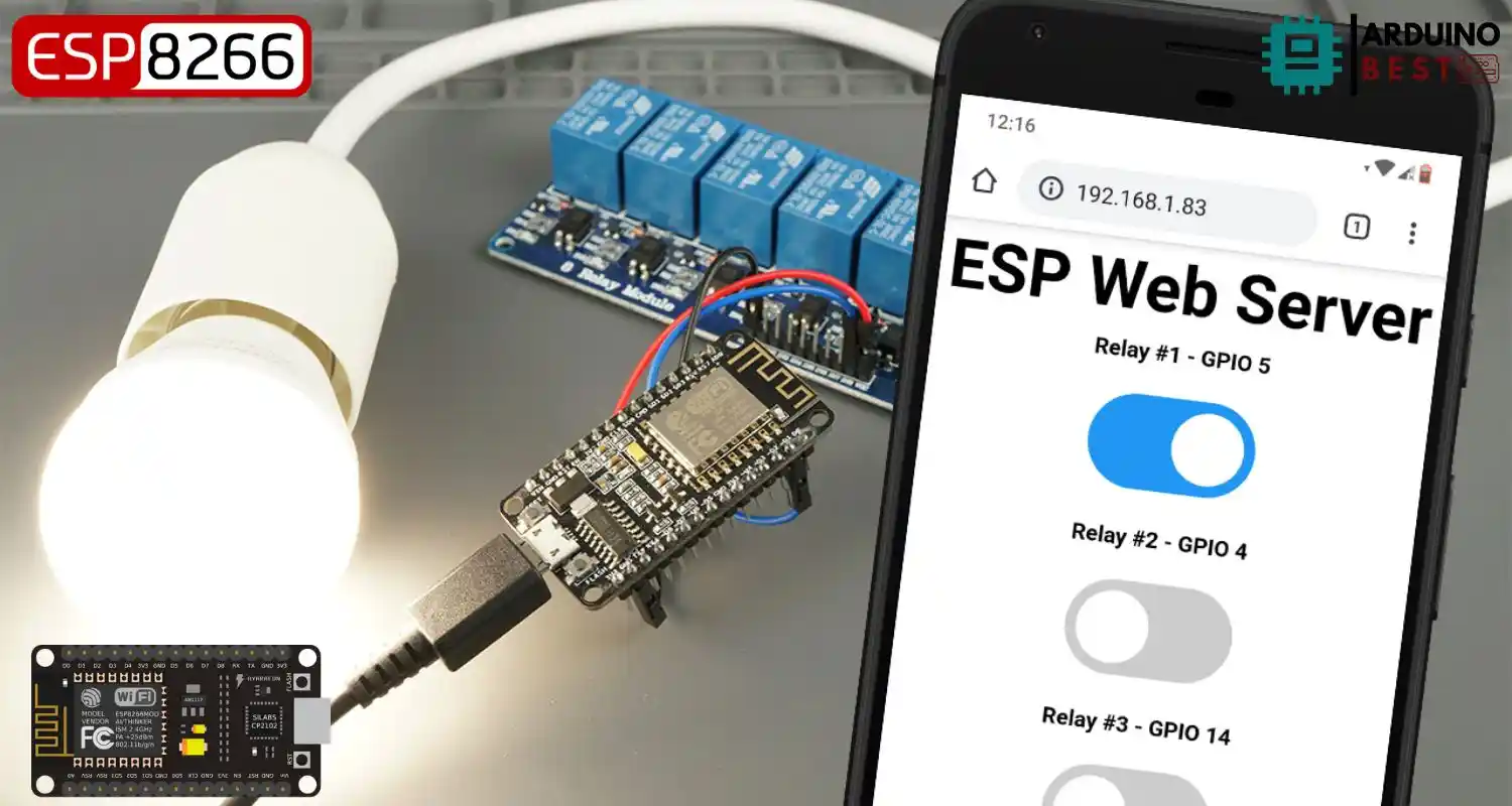
The rise of home automation has transformed how we interact with everyday appliances. Using an ESP8266 NodeMCU and a relay module, it’s now possible to control AC appliances remotely via a simple web server. This tutorial shows you exactly how to make it happen, even if you’re just getting started with IoT projects.
What Is ESP8266 NodeMCU?
The ESP8266 NodeMCU is a low-cost Wi-Fi-enabled microcontroller perfect for building smart automation systems. It offers:
- Built-in Wi-Fi capabilities
- Multiple GPIO pins for controlling external devices
- Compatibility with the Arduino IDE
Compared to traditional Arduino boards, the ESP8266 shines with its wireless communication capabilities, making it a go-to choice for connected applications.
If you’re unfamiliar with pin mapping, check this ESP8266 GPIO reference for details on which pins are safe and recommended for use.
What is a Relay Module and How Does It Work?
A relay module acts as an electrically operated switch, allowing low-voltage digital signals to control high-voltage AC devices safely. Key features include:
- Multiple channels (1, 2, 4, 8, or 16 relays)
- Built-in optocouplers for isolation between control and power circuits
- COM (Common), NO (Normally Open), and NC (Normally Closed) terminals
To learn more about the internal workings, explore how relays function in circuits.
Safety First: Working with AC Appliances
Handling mains voltage is dangerous if not done properly. Before wiring an AC appliance:
- Always disconnect power before touching connections
- Use heat-shrink tubing or electrical insulation
- Avoid working directly with high voltage unless you’re experienced
- Start by using low-voltage devices (like 12V lights) for testing
Components Required
Before starting the project, gather the following:
- ESP8266 NodeMCU board
- Relay module (1-channel or more)
- An AC appliance (lamp, fan, etc.)
- Jumper wires, breadboard, USB cable
- Arduino IDE installed on your computer
Install ESP8266 board in Arduino IDE
Connecting the Relay Module to ESP8266
Here’s how to wire the relay module to the ESP8266:
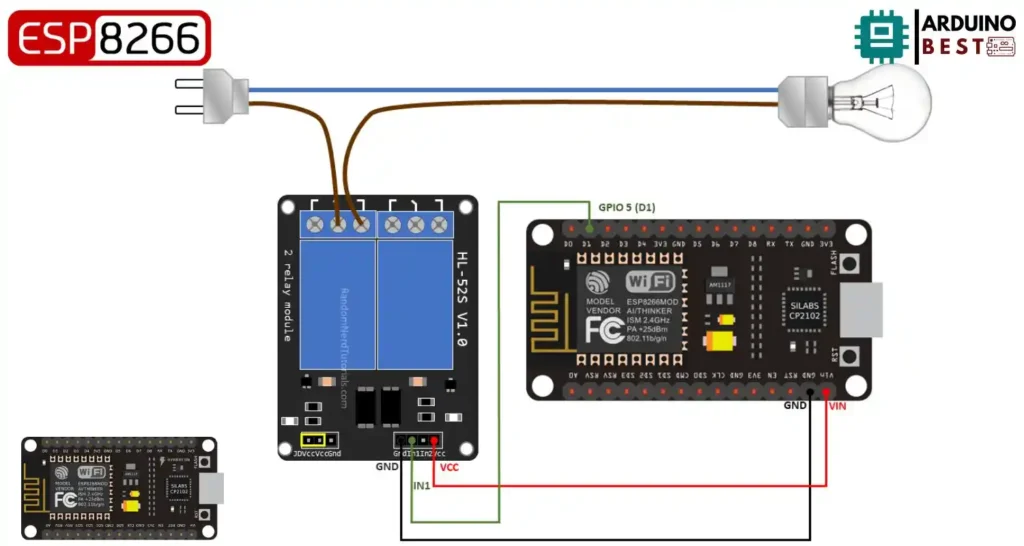
- Connect VCC of the relay to 3.3V on ESP8266 (or external 5V with optocoupler)
- GND to GND
- IN pin to a GPIO pin (e.g., D1 or GPIO5)
- AC appliance connected to COM and NO (Normally Open) terminals
Note: Use a proper power source if driving more than one relay.
Writing the Arduino Sketch
With the hardware wired up, the next step is coding.
- Use Arduino IDE to program the ESP8266
- Include necessary libraries:
ESP8266WiFi.h,ESP8266WebServer.h - Define your GPIO pin used for the relay
- Set up Wi-Fi connection
- Create HTTP routes to handle ON/OFF requests
Here’s a basic snippet:
digitalWrite(relayPin, HIGH); // Turns ON
digitalWrite(relayPin, LOW);  // Turns OFF
This code allows you to toggle the appliance from your web interface.
Building a Web Server Interface
With the ESP8266 hosting a simple web server, you can interact via a browser.
- Create a basic HTML page with two buttons: ON and OFF
- Link the buttons to ESP8266 endpoints (
/on,/off) - Use
ESP8266WebServeror ESPAsyncWebServer for efficient handling of requests
Your interface can look like this:
#include "ESP8266WiFi.h"
#include "ESPAsyncWebServer.h"

// Set to true to define Relay as Normally Open (NO)
#define RELAY_NO    true

// Set number of relays
#define NUM_RELAYS  5

// Assign each GPIO to a relay
int relayGPIOs[NUM_RELAYS] = {5, 4, 14, 12, 13};

// Replace with your network credentials
const char* ssid = "REPLACE_WITH_YOUR_SSID";
const char* password = "REPLACE_WITH_YOUR_PASSWORD";

const char* PARAM_INPUT_1 = "relay";
const char* PARAM_INPUT_2 = "state";

// Create AsyncWebServer object on port 80
AsyncWebServer server(80);

const char index_html[] PROGMEM = R"rawliteral(
<!DOCTYPE HTML><html>
<head>
  <meta name="viewport" content="width=device-width, initial-scale=1">
  <style>
    html {font-family: Arial; display: inline-block; text-align: center;}
    h2 {font-size: 3.0rem;}
    p {font-size: 3.0rem;}
    body {max-width: 600px; margin:0px auto; padding-bottom: 25px;}
    .switch {position: relative; display: inline-block; width: 120px; height: 68px}
    .switch input {display: none}
    .slider {position: absolute; top: 0; left: 0; right: 0; bottom: 0; background-color: #ccc; border-radius: 34px}
    .slider:before {position: absolute; content: ""; height: 52px; width: 52px; left: 8px; bottom: 8px; background-color: #fff; -webkit-transition: .4s; transition: .4s; border-radius: 68px}
    input:checked+.slider {background-color: #2196F3}
    input:checked+.slider:before {-webkit-transform: translateX(52px); -ms-transform: translateX(52px); transform: translateX(52px)}
  </style>
</head>
<body>
  <h2>ESP Web Server</h2>
  %BUTTONPLACEHOLDER%
<script>function toggleCheckbox(element) {
  var xhr = new XMLHttpRequest();
  if(element.checked){ xhr.open("GET", "/update?relay="+element.id+"&state=1", true); }
  else { xhr.open("GET", "/update?relay="+element.id+"&state=0", true); }
  xhr.send();
}</script>
</body>
</html>
)rawliteral";

// Replaces placeholder with button section in your web page
String processor(const String& var){
  //Serial.println(var);
  if(var == "BUTTONPLACEHOLDER"){
    String buttons ="";
    for(int i=1; i<=NUM_RELAYS; i++){
      String relayStateValue = relayState(i);
      buttons+= "<h4>Relay #" + String(i) + " - GPIO " + relayGPIOs[i-1] + "</h4><label class=\"switch\"><input type=\"checkbox\" onchange=\"toggleCheckbox(this)\" id=\"" + String(i) + "\" "+ relayStateValue +"><span class=\"slider\"></span></label>";
    }
    return buttons;
  }
  return String();
}

String relayState(int numRelay){
  if(RELAY_NO){
    if(digitalRead(relayGPIOs[numRelay-1])){
      return "";
    }
    else {
      return "checked";
    }
  }
  else {
    if(digitalRead(relayGPIOs[numRelay-1])){
      return "checked";
    }
    else {
      return "";
    }
  }
  return "";
}

void setup(){
  // Serial port for debugging purposes
  Serial.begin(115200);

  // Set all relays to off when the program starts - if set to Normally Open (NO), the relay is off when you set the relay to HIGH
  for(int i=1; i<=NUM_RELAYS; i++){
    pinMode(relayGPIOs[i-1], OUTPUT);
    if(RELAY_NO){
      digitalWrite(relayGPIOs[i-1], HIGH);
    }
    else{
      digitalWrite(relayGPIOs[i-1], LOW);
    }
  }

  // Connect to Wi-Fi
  WiFi.begin(ssid, password);
  while (WiFi.status() != WL_CONNECTED) {
    delay(1000);
    Serial.println("Connecting to WiFi..");
  }

  // Print ESP8266 Local IP Address
  Serial.println(WiFi.localIP());

  // Route for root / web page
  server.on("/", HTTP_GET, [](AsyncWebServerRequest *request){
    request->send(200, "text/html", index_html, processor);
  });

  // Send a GET request to <ESP_IP>/update?relay=<inputMessage>&state=<inputMessage2>
  server.on("/update", HTTP_GET, [] (AsyncWebServerRequest *request) {
    String inputMessage;
    String inputParam;
    String inputMessage2;
    String inputParam2;
    // GET input1 value on <ESP_IP>/update?relay=<inputMessage>
    if (request->hasParam(PARAM_INPUT_1) & request->hasParam(PARAM_INPUT_2)) {
      inputMessage = request->getParam(PARAM_INPUT_1)->value();
      inputParam = PARAM_INPUT_1;
      inputMessage2 = request->getParam(PARAM_INPUT_2)->value();
      inputParam2 = PARAM_INPUT_2;
      if(RELAY_NO){
        Serial.print("NO ");
        digitalWrite(relayGPIOs[inputMessage.toInt()-1], !inputMessage2.toInt());
      }
      else{
        Serial.print("NC ");
        digitalWrite(relayGPIOs[inputMessage.toInt()-1], inputMessage2.toInt());
      }
    }
    else {
      inputMessage = "No message sent";
      inputParam = "none";
    }
    Serial.println(inputMessage + inputMessage2);
    request->send(200, "text/plain", "OK");
  });
  // Start server
  server.begin();
}

void loop() {

}
Expanding to Multiple Relays
Want to control multiple appliances?
- Connect additional relays to unused GPIOs
- Update the Arduino sketch to include multiple endpoints
- Modify the web interface to show buttons for each device
For instance, using D1, D2, and D3 to control three relays individually.
Adding Security to the Web Server
To avoid unauthorized access:
- Add basic HTTP authentication to your web server
- Use strong passwords and change default network credentials
- Avoid exposing the device directly to the internet
Bonus Tip: Use a captive portal or local network IP restrictions for added protection.
Troubleshooting Common Issues
Here’s how to solve typical problems:
- Relay not clicking? Check GPIO logic level; some modules are LOW triggered
- Web server unresponsive? Check Wi-Fi credentials and re-upload code
- Appliance not switching? Confirm relay connection to NO/COM terminals
Monitor serial output via Arduino IDE to debug responses.
Real-World Applications
The project opens up many real-world automation ideas:
- Control room lighting and ceiling fans
- Remote start coffee machines or air conditioners
- Automate outdoor lighting with timers
- Integrate with smart home assistants via MQTT or IFTTT
FAQs
How do I control AC appliances with ESP8266?
Use a relay module to safely switch the AC appliance on or off using ESP8266’s digital GPIO signals, controlled through a web interface.
Is it safe to use ESP8266 with AC appliances?
Yes, if proper isolation is used through optocouplers and if safety precautions are followed strictly.
Can I control multiple appliances with one ESP8266?
Yes, by using a multi-channel relay module and connecting each to a different GPIO pin.
What is the difference between NO and NC terminals?
- NO (Normally Open): Circuit is OFF by default, closes when relay is activated
- NC (Normally Closed): Circuit is ON by default, opens when relay is activated
How can I secure my ESP8266 web server?
Implement basic authentication, use secure passwords, and restrict access to local networks only.
Conclusion
By combining the ESP8266 NodeMCU with a relay module, you can easily control AC appliances via a browser, creating powerful and flexible home automation solutions. With simple code and a minimal setup, you’re well on your way to building a smarter home or lab project.
Stay safe, start simple, and continue exploring the endless possibilities of IoT and web-based automation.
Projects ESP8266 nodemcu
1- ESP8266 NodeMCU: A Comprehensive Guide to IoT Development
2- Control LED with ESP8266 NodeMCU: A Beginner’s Guide
3- Integrating a Joystick with ESP8266 NodeMCU: A Comprehensive Guide
4- esp8266 nodemcu with Flame Sensor
5- ESP8266 NodeMCU with Heartbeat Sensor
6- ESP8266 NodeMCU with KY-027 Magic Cup Light
7- ESP8266 NodeMCU with Hall Magnetic Sensor
8- ESP8266 NodeMCU with relay module 5v
9- ESP8266 NodeMCU with Linear Hall Sensor