Table of Contents
Introduction to Home Automation
Home automation refers to the automatic and electronic control of household features, activities, and appliances. It allows homeowners to manage devices remotely, leading to increased convenience, energy efficiency, and security. Traditional systems often rely on a single control method, but integrating multiple interfaces—such as smartphones, infrared (IR) remotes, and manual controls—offers enhanced flexibility.
Understanding Arduino in Home Automation
Arduino is an open-source electronics platform based on simple hardware and software. It’s widely used in DIY projects due to its affordability and ease of use. In home automation, Arduino serves as the central hub, processing inputs from various control methods and managing the operation of connected devices.
Infrared (IR) Communication in Home Automation
Infrared communication involves transmitting data using IR light waves, commonly employed in remote controls for TVs and other appliances. Incorporating IR communication into home automation allows for the control of devices using standard IR remotes. This method is cost-effective and leverages existing technology.Arduino Forum
Integrating Smartphone Control in Home Automation
Smartphones can communicate with Arduino using Bluetooth or Wi-Fi modules, enabling users to control home appliances through dedicated apps. This integration offers the convenience of managing devices from anywhere within the network range. For instance, using a Bluetooth module like the HC-05 allows seamless communication between the smartphone and Arduino.Instructables
Manual Control in Automated Systems
Despite the advantages of remote control, manual switches remain essential for immediate and reliable operation. Integrating physical buttons ensures that devices can still be controlled without relying solely on electronic interfaces, providing a fail-safe mechanism.
Components Required for Arduino-Based Home Automation
To build a versatile home automation system, you’ll need the following components:
- Arduino Board: Serves as the central controller.
- IR Receiver and Transmitter Modules: Facilitate communication with IR remotes.
- Bluetooth Module (e.g., HC-05): Enables smartphone connectivity.YouTube+6Arduino Forum+6YouTube+6
- Relay Modules: Control high-voltage appliances safely.
- Manual Switches: Allow physical control of devices.Arduino Forum+3Arduino Forum+3Arduino Forum+3
- Power Supply: Provides necessary power to the system.Instructables+1Instructables+1
Setting Up the Hardware
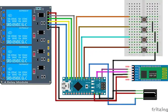
- Connect the IR Receiver: Attach the IR receiver module to the Arduino, ensuring proper alignment of power, ground, and signal pins.
- Integrate the Bluetooth Module: Connect the HC-05 module to the Arduino’s serial pins for smartphone communication.
- Wire the Relay Modules: Connect relay modules to control high-voltage appliances, ensuring safety precautions are in place.
- Install Manual Switches: Set up physical switches parallel to the relay controls for manual operation.
Circuit diagram

Programming the Arduino for IR Remote Control
To enable IR control, install the IRremote library in the Arduino IDE. This library allows decoding signals from an IR remote and mapping them to specific actions. By capturing the unique codes transmitted by each button, you can program the Arduino to respond accordingly. Detailed guidance on setting up and mapping buttons is available in this Arduino IR Remote Controller Tutorial.InstructablesRobotics Backend
Code arduino
#include <SPI.h>
#include <Wire.h>
#include <EEPROM.h>
#include <IRremote.h>
String readString;

 int relay_1 = 12;
 int relay_2 = 11;
 int relay_3 = 10;
 int relay_4 = 9;

const int mswitch_1 = 8;
const int mswitch_2 = 7;
const int mswitch_3 = 6;
const int mswitch_4 = 5;

int RECV_PIN = 3;

IRrecv irrecv(RECV_PIN);
decode_results results;


int toggleState_1 = 0;
int toggleState_2 = 0;
int toggleState_3 = 0;
int toggleState_4 = 0;

void setup() {

  Serial.begin(9600);
  irrecv.enableIRIn();

  pinMode(relay_1, OUTPUT);
  pinMode(relay_2, OUTPUT);
  pinMode(relay_3, OUTPUT);
  pinMode(relay_4, OUTPUT);

  pinMode(mswitch_1, INPUT_PULLUP);
  pinMode(mswitch_2, INPUT_PULLUP);
  pinMode(mswitch_3, INPUT_PULLUP);
  pinMode(mswitch_4, INPUT_PULLUP);

  eepromcheckstate();
}

void relayOnOff(int relay){

 switch(relay){
      case 1:
             if(toggleState_1 == 0){
              digitalWrite(relay_1, HIGH); // turn on relay 1
              EEPROM.update(0,HIGH);
              toggleState_1 = 1;
              }
             else{
              digitalWrite(relay_1, LOW); // turn off relay 1
              EEPROM.update(0,LOW);
              toggleState_1 = 0;
              }
             delay(100);
      break;
      case 2:
             if(toggleState_2 == 0){
              digitalWrite(relay_2, HIGH); // turn on relay 2
              EEPROM.update(1,HIGH);
              toggleState_2 = 1;
              }
             else{
              digitalWrite(relay_2, LOW); // turn off relay 2
              EEPROM.update(1,LOW);
              toggleState_2 = 0;
              }
             delay(100);
      break;
      case 3:
             if(toggleState_3 == 0){
              digitalWrite(relay_3, HIGH); // turn on relay 3
              EEPROM.update(2,HIGH);
              toggleState_3 = 1;
              }else{
              digitalWrite(relay_3, LOW); // turn off relay 3
              EEPROM.update(2,LOW);
              toggleState_3 = 0;
              }
             delay(100);
      break;
      case 4:
             if(toggleState_4 == 0){
              digitalWrite(relay_4, HIGH); // turn on relay 4
              EEPROM.update(3,HIGH);
              toggleState_4 = 1;
              }
             else{
              digitalWrite(relay_4, LOW); // turn off relay 4
              EEPROM.update(3,LOW);
              toggleState_4 = 0;
              }
             delay(100);
      break;

      default : break;
      }

}

void eepromcheckstate()
{

  toggleState_1 = EEPROM.read(0);
  if(toggleState_1 == HIGH) {
    digitalWrite(relay_1, HIGH);
   }
   if(toggleState_1 == LOW) {
    digitalWrite(relay_1, LOW);
   }

  toggleState_2 = EEPROM.read(1);
  if(toggleState_2 == HIGH) {
    digitalWrite(relay_2, HIGH);
   }
   if(toggleState_2 == LOW) {
    digitalWrite(relay_2, LOW);
   }

  toggleState_3 = EEPROM.read(2);
  if(toggleState_3 == HIGH) {
    digitalWrite(relay_3, HIGH);
   }
   if(toggleState_3 == LOW) {
    digitalWrite(relay_3, LOW);
   }

  toggleState_4 = EEPROM.read(3);
  if(toggleState_4 == HIGH) {
    digitalWrite(relay_4, HIGH);
   }
   if(toggleState_4 == LOW) {
    digitalWrite(relay_4, LOW);
   }

}

void loop() {

    if (digitalRead(mswitch_1) == LOW){
      delay(200);
      relayOnOff(1);
    }
    else if (digitalRead(mswitch_2) == LOW){
      delay(200);
      relayOnOff(2);
    }
    else if (digitalRead(mswitch_3) == LOW){
      delay(200);
      relayOnOff(3);
    }
    else if (digitalRead(mswitch_4) == LOW){
      delay(200);
      relayOnOff(4);
    }


if (irrecv.decode(&results)) {
        switch(results.value){
          case 0x14EB58A7:
                    relayOnOff(1);
          break;
          case 0x14EB8877:
                    relayOnOff(2);
          break;
          case 0x14EB906F:
                    relayOnOff(3);
          break;
          case 0x14EBD827:
                    relayOnOff(4);
          break;
          default : break;
          }
    irrecv.resume();
    }


      while(Serial.available())    //Check if there are available bytes to read
  {
    delay(10);                 //Delay to make it stable
    char c = Serial.read();    //Conduct a serial read
    if (c == '#'){
      break;                   //Stop the loop once # is detected after a word
    }
    readString += c;                //Means readString = readString + c
  }
    if (readString.length() >0)
    {
      Serial.println(readString);

      if(readString == "RELAY1"){
        relayOnOff(1);
      }
      else if(readString == "RELAY2"){
        relayOnOff(2);
      }
      else if(readString == "RELAY3"){
        relayOnOff(3);
      }
      else if(readString == "RELAY4"){
        relayOnOff(4);
      }
      readString="";
    }
  }
Developing Smartphone Control Interface
For smartphone control, a compatible app is required to send commands via Bluetooth. Apps like “Arduino Bluetooth Controller” can be used to create custom interfaces. The Arduino code should handle incoming Bluetooth signals and trigger corresponding actions, allowing seamless control of appliances from your smartphone.
Implementing Manual Controls
Manual switches are connected to the Arduino’s digital input pins. The code should monitor these inputs and activate the corresponding relays when a switch is toggled. This setup ensures that appliances can be controlled directly without relying on remote interfaces.
Combining Control Methods for Seamless Operation
Integrating IR, smartphone, and manual controls requires careful programming to manage inputs from multiple sources. The Arduino code should prioritize inputs and handle conflicts to ensure smooth operation. Implementing a state machine can help manage the different control methods effectively.
Testing and Troubleshooting the System
After setting up the hardware and uploading the code:
- Test Each Control Method: Verify that IR, smartphone, and manual controls operate as intended.
- Check for Conflicts: Ensure that inputs from different sources do not interfere with each other.
- Monitor System Stability: Observe the system’s response over time to identify any reliability issues.
Enhancements and Future Developments
Consider expanding the system with additional features:
- Voice Control Integration: Incorporate voice assistants like Alexa or Google Home for hands-free operation.
- Scheduling Functions: Program the system to operate appliances based on predefined schedules.
- Remote Access: Enable control over the internet for access outside the local network.
FAQs
How do I find the IR codes for my appliances?
Use the Arduino and an IR receiver module to capture and decode signals from your existing remote controls. This process involves pressing buttons on the remote and recording the corresponding codes received by the Arduino.
Can I control multiple devices with a single Arduino board?
Yes, an Arduino can manage multiple devices by assigning different pins to control various relays and handling multiple input methods in the code.
Conclusion
An Arduino-based home automation system that combines smartphone, IR remote, and manual control offers an incredibly versatile, flexible, and educational platform for makers of all levels. This kind of setup allows you to interact with your appliances in multiple ways—remotely via Bluetooth, traditionally via IR remotes, or physically using manual switches—catering to different user preferences and accessibility needs.
One of the biggest advantages of this project is its customizability. Whether you’re just starting out or have advanced electronics skills, you can scale and enhance this system over time. Add voice control, Wi-Fi integration, or sensor-based automation to create a more robust and intelligent smart home.
By diving into this project, you’re not just automating your devices—you’re learning about embedded systems, programming logic, sensor integration, and wireless communication. It’s an excellent hands-on experience that boosts your skills in electronics and IoT development.
So start building your system today. Tweak it, expand it, and make it truly yours. With Arduino, the possibilities for DIY home automation are endless—and the best part? You’re the architect of your smart home’s future. 🏠💡🔧
Arduino Projects:
1- Complete Guide for DHT11/DHT22 Humidity and Temperature Sensor With Arduino
2- DHT11 – Temperature and Humidity Sensor
3- DHT22 – Temperature and Humidity Sensor (more accurate than DHT11)
4- BMP180 – Barometric Pressure and Altitude Sensor
5- BMP280 – Barometric Pressure & Temperature Sensor
6- BME280 – Temperature, Humidity, and Pressure Sensor
7- Arduino Flex Sensor Controlled Robot Hand
8- Arduino ECG Heart Rate Monitor AD8232 Demo
9- Arduino NRF24L01 Wireless Joystick Robot Car
10- Arduino Force Sensor Anti-Theft Alarm System
11- Arduino NRF24L01 Transceiver Controlled Relay Light
12- Arduino Rotary Encoder Controlled LEDs: A Complete Guide

