Table of Contents
Introduction
In today’s world, ensuring the security of your home or office is paramount. Traditional locks are being replaced with smarter solutions, and one of the most innovative options is the Arduino RFID Door Lock System. This system provides a unique, tech-savvy approach to access control by using RFID technology and an LCD display for easy interaction.
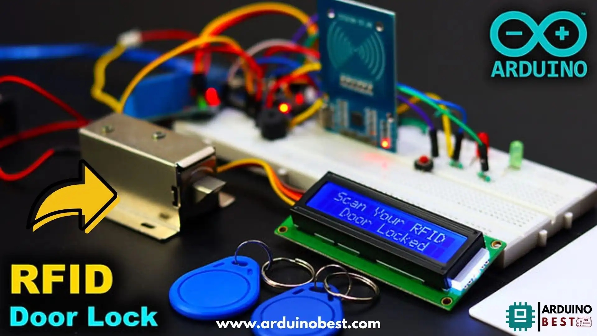
The Arduino RFID Door Lock system operates by reading RFID tags to authenticate the user, and when successful, it activates the solenoid lock to grant access. The LCD display shows real-time status updates, indicating whether access has been granted or denied. The integration of these components with Arduino makes this project accessible for beginners while offering plenty of room for enhancements.
For a more in-depth explanation of how RFID works, you can check out this detailed guide on the MFRC522 RFID module, which will help you understand how it interacts with Arduino. By using this guide, you’ll understand the heart of the project: RFID communication.
Components Required
Building an Arduino RFID Door Lock System requires several key components, each playing a vital role in the functionality of the system. Here is a list of what you’ll need:
- Arduino UNO – Acts as the central processing unit for the project.
- MFRC522 RFID Module – This module reads the RFID tags.
- 16×2 LCD Display (I2C) – Provides user-friendly visual feedback.
- Relay Module – Controls the power to the solenoid lock.
- Solenoid Lock – The lock mechanism that is controlled by the relay.
- Jumper Wires and Breadboard – For easy circuit connections.
- Power Supply – To power your Arduino and peripherals.
For wiring and assembly, this page on setting up your Arduino RFID Door Lock will guide you through step-by-step instructions.
Circuit Design and Assembly
Now that you have your components, it’s time to assemble the system. The circuit design is relatively simple, but attention to detail is essential to ensure everything functions smoothly.
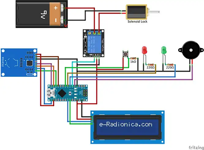
Schematic Diagram

Creating a schematic diagram helps you visualize the connections. Below are the primary connections:
- MFRC522 RFID Module:
- SDA pin to Arduino Pin 10
- SCK pin to Arduino Pin 13
- MOSI pin to Arduino Pin 11
- MISO pin to Arduino Pin 12
- IRQ and GND connected to ground
- RST to Pin 9
- LCD Display:
- VCC to 5V
- GND to GND
- SDA and SCL to A4 and A5 respectively (I2C)
- Relay Module:
- IN pin to Arduino Pin 8
- VCC to 5V
- GND to GND
- NO (Normally Open) pin connected to the solenoid lock.
By using the MFRC522 RFID Module Guide, you’ll ensure that your RFID module is properly integrated.
Arduino Code Implementation
The programming aspect is where the magic happens! Below is a breakdown of the Arduino code:
Required Libraries
To get started, you will need the following libraries:
#include <SPI.h>
#include <MFRC522.h>
#include <Wire.h>
#include <LiquidCrystal_I2C.h>
Code Overview
Here’s a simple breakdown of what the code does:
- Initializes the RFID module, LCD, and relay.
- Reads the RFID tag when placed near the RFID reader.
- Compares the read RFID tag against stored authorized tags.
- Activates the relay to unlock the solenoid lock if the tag is authorized.
- Displays messages like “Access Granted” or “Access Denied” on the LCD screen.
Example Code
#include <Wire.h>
#include <SPI.h>
#include <MFRC522.h>
#include <LiquidCrystal_I2C.h>
LiquidCrystal_I2C lcd(0x3F, 16, 2);

#define SS_PIN 10
#define RST_PIN 9
#define LED_G 4 //define green LED pin
#define LED_R 5 //define red LED
#define BUZZER 2 //buzzer pin
#define lock 3
MFRC522 mfrc522(SS_PIN, RST_PIN);   // Create MFRC522 instance.
int Btn = 6;

void setup()
{
  Serial.begin(9600);   // Initiate a serial communication
  SPI.begin();      // Initiate  SPI bus
  mfrc522.PCD_Init();   // Initiate MFRC522
  pinMode(LED_G, OUTPUT);
  pinMode(LED_R, OUTPUT);
  pinMode(BUZZER, OUTPUT);
  noTone(BUZZER);
  pinMode(Btn,INPUT);
  pinMode(lock,OUTPUT);
  Serial.println("Place your card on reader...");
  Serial.println();
  lcd.begin();
  lcd.backlight();
  lcd.clear();
  lcd.setCursor(0,0); // column, row
  lcd.print(" Scan Your RFID ");
  lcd.setCursor(0,1); // column, row
  lcd.print("   Door Locked   ");

 }
void loop()
{

if(digitalRead(Btn) == HIGH){

    Serial.println("Access Granted");
    Serial.println();
    delay(500);
    digitalWrite(LED_G, HIGH);
    lcd.setCursor(0,1); // column, row
    lcd.print(" Door Un-Locked ");
    tone(BUZZER, 2000);
    delay(100);
    noTone(BUZZER);
    delay(50);
    tone(BUZZER, 2000);
    delay(100);
    noTone(BUZZER);
    digitalWrite(lock,HIGH);
    delay(3000);
    digitalWrite(lock,LOW);
    delay(100);
    digitalWrite(LED_G, LOW);
    lcd.setCursor(0,1); // column, row
    lcd.print("   Door Locked   ");
    tone(BUZZER, 2000);
    delay(100);
    noTone(BUZZER);
  delay(50);
  }


  // Look for new cards
  if ( ! mfrc522.PICC_IsNewCardPresent())
  {
    return;
  }
  // Select one of the cards
  if ( ! mfrc522.PICC_ReadCardSerial())
  {
    return;
  }
  //Show UID on serial monitor
  Serial.print("UID tag :");
  String content= "";
  byte letter;
  for (byte i = 0; i < mfrc522.uid.size; i++)
  {
     Serial.print(mfrc522.uid.uidByte[i] < 0x10 ? " 0" : " ");
     Serial.print(mfrc522.uid.uidByte[i], HEX);
     content.concat(String(mfrc522.uid.uidByte[i] < 0x10 ? " 0" : " "));
     content.concat(String(mfrc522.uid.uidByte[i], HEX));
  }
  Serial.println();
  Serial.print("Message : ");
  content.toUpperCase();


 if (content.substring(1) == "83 23 38 BB") //change here the UID of card/cards or tag/tags that you want to give access
  {
    Serial.println("Access Granted");
    Serial.println();
    delay(500);
    digitalWrite(LED_G, HIGH);
    lcd.setCursor(0,1); // column, row
    lcd.print(" Door Un-Locked ");
    tone(BUZZER, 2000);
    delay(100);
    noTone(BUZZER);
    delay(50);
    tone(BUZZER, 2000);
    delay(100);
    noTone(BUZZER);
    digitalWrite(lock,HIGH);
    delay(3000);
    digitalWrite(lock,LOW);
    delay(100);
    digitalWrite(LED_G, LOW);
    lcd.setCursor(0,1); // column, row
    lcd.print("   Door Locked   ");
    tone(BUZZER, 2000);
    delay(100);
    noTone(BUZZER);
    delay(50);
  }

else
{
    lcd.setCursor(0,1); // column, row
    lcd.print("Invalid RFID Tag");
    Serial.println(" Access denied");
    digitalWrite(LED_R, HIGH);
    tone(BUZZER, 1500);
    delay(500);
    digitalWrite(LED_R, LOW);
    noTone(BUZZER);
    delay(100);
    digitalWrite(LED_R, HIGH);
    tone(BUZZER, 1500);
    delay(500);
    digitalWrite(LED_R, LOW);
    noTone(BUZZER);
    delay(100);
    digitalWrite(LED_R, HIGH);
    tone(BUZZER, 1500);
    delay(500);
    digitalWrite(LED_R, LOW);
    noTone(BUZZER);
    lcd.setCursor(0,1); // column, row
    lcd.print("   Door Locked   ");
 }
 }
For more details on the code, check out this Instructable on DIY RFID Door Locks.
Testing and Calibration
Once the hardware is assembled and the code is uploaded to your Arduino, it’s time for testing:
- Check Connections: Ensure that all components are connected correctly according to the schematic.
- Upload the Code: Use the Arduino IDE to upload the code to your board.
- Test the RFID Tags: Hold an RFID tag near the reader. If it’s authorized, the door will unlock.
- Verify LCD Output: The LCD should display “Access Granted” for authorized tags and “Access Denied” for others.
Troubleshooting Tips
- If the RFID tag is not recognized, check your Wiring and Library installations.
- If the solenoid lock doesn’t work, make sure the Relay Module is connected properly to the Arduino.
Enhancements and Customizations
Once you have the basic RFID lock working, there are many ways to customize and enhance your system:
- Multiple RFID Tags: Store multiple tag IDs in Arduino memory and allow various people to unlock the door.
- PIN Code Authentication: Combine RFID with a keypad for dual authentication.
- Wi-Fi Integration: Use a Wi-Fi module like the ESP8266 to enable remote unlocking.
- Sound Alerts: Add a buzzer for feedback when the door is locked or unlocked.
For further information, this post explores some of these ideas.
Safety and Security Considerations
- Privacy of Data: Ensure that the RFID tag information is not easily accessible.
- Solenoid Lock Security: Make sure the lock mechanism is robust enough to prevent tampering.
- Backup Power: Use a battery or uninterruptible power supply (UPS) to ensure the system continues to work during power outages.
FAQs
How does RFID authentication work in this system?
RFID authentication works by reading the unique ID stored in the RFID tag. If the tag matches the authorized tag, access is granted.
Can I use this system for multiple doors?
Yes, you can replicate this system for multiple doors by adjusting the Arduino code and adding more solenoid locks.
What if I lose my RFID tag?
You can easily add or remove tags by reprogramming the Arduino with the new tag IDs.
How secure is this system?
While RFID tags are fairly secure, combining the system with a keypad or fingerprint scanner can further enhance security.
Can I integrate this with my home automation system?
Yes, with a Wi-Fi module like the ESP8266, you can integrate the system with your existing home automation setup.
Conclusion
The Arduino RFID Door Lock System with an LCD display is an excellent project that combines security with convenience. By leveraging RFID technology and the versatility of Arduino, this system provides a simple yet effective solution for controlling access to your home or office. Whether you’re a beginner or an advanced maker, building this system offers a hands-on experience in electronics, programming, and security systems.
This project not only enhances the security of your space but also provides opportunities for further customization and enhancement. You can integrate additional features like multiple RFID tag support, PIN code authentication, remote control via Wi-Fi, and even integration with home automation systems.
What’s exciting about this project is its scalability—there’s always room for improvement and innovation. The combination of affordable components like the MFRC522 RFID module, LCD display, and Arduino board makes this an accessible DIY project for anyone interested in creating smart security solutions.
Start building today, and take the first step toward exploring the possibilities of DIY smart access control and security systems. With the right tools and creativity, the potential applications of this system are limitless!
Arduino Projects:
1- Complete Guide for DHT11/DHT22 Humidity and Temperature Sensor With Arduino
2- DHT11 – Temperature and Humidity Sensor
3- DHT22 – Temperature and Humidity Sensor (more accurate than DHT11)
4- BMP180 – Barometric Pressure and Altitude Sensor
5- BMP280 – Barometric Pressure & Temperature Sensor
6- BME280 – Temperature, Humidity, and Pressure Sensor
7- Arduino Flex Sensor Controlled Robot Hand
8- Arduino ECG Heart Rate Monitor AD8232 Demo
9- Arduino NRF24L01 Wireless Joystick Robot Car
10- Arduino Force Sensor Anti-Theft Alarm System
11- Arduino NRF24L01 Transceiver Controlled Relay Light
12- Arduino Rotary Encoder Controlled LEDs: A Complete Guide

