Table of Contents
Introduction
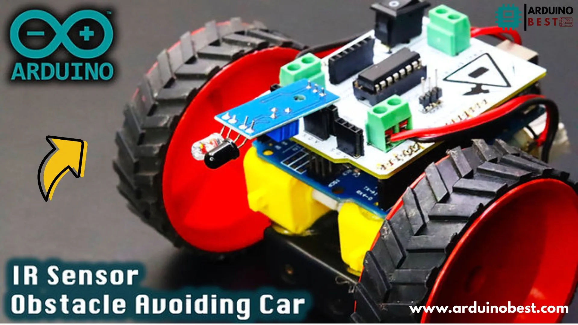
Building an obstacle-avoiding robot is a fun and educational way to learn about Arduino, IR sensors, and motor control. These robots use infrared (IR) sensors to detect obstacles and adjust their movement automatically. With an L293D motor driver shield, we can efficiently control the motors and make our robot move autonomously.
In this guide, we will cover how to build an Arduino-based obstacle-avoiding robot using an IR sensor and L293D motor driver shield. We’ll go through circuit design, programming, and troubleshooting to ensure you can successfully complete your project.
Components Required
To build the obstacle-avoiding robot, you will need the following components:
- Arduino Uno – The microcontroller that processes sensor data.
- IR Obstacle Avoidance Sensors – Detect obstacles in front of the robot.
- L293D Motor Driver Shield – Controls the DC motors.
- Two DC Motors and Wheels – Enables movement of the robot.
- Chassis – Holds all components together.
- Power Supply (9V Battery or Li-ion Battery Pack) – Powers the Arduino and motors.
- Jumper Wires – Connect various components.
- Breadboard (Optional) – Helps in circuit prototyping.
How IR Sensors Work in Obstacle Avoidance
IR sensors work on the principle of infrared light reflection. They emit IR rays, which bounce back when they hit an obstacle. The sensor then calculates the distance and determines whether the object is close enough to require an action.
Advantages of IR Sensors:
- Low cost and easy to use
- Can detect obstacles at short distances
- Consumes minimal power
Circuit Design & Wiring

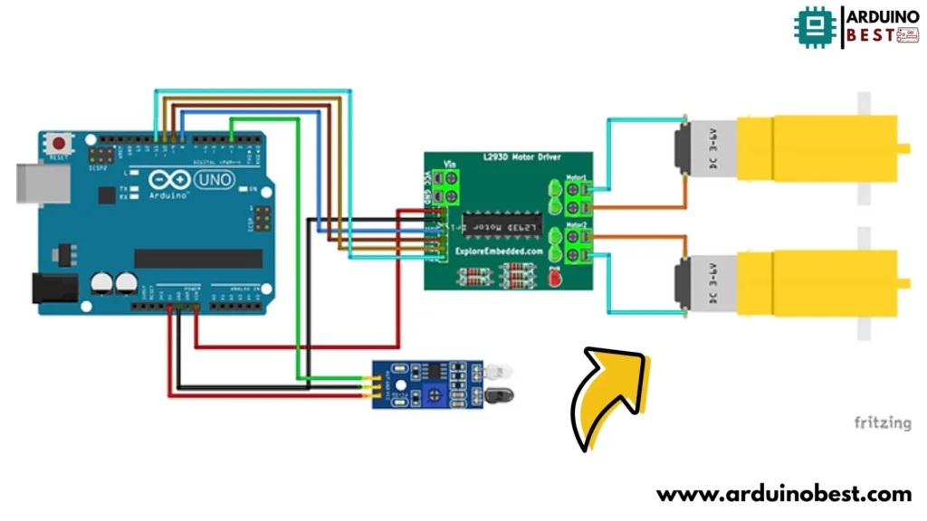
To assemble the robot, follow these wiring instructions:
- Connecting the IR Sensors to Arduino
- VCC → 5V on Arduino
- GND → GND on Arduino
- OUT → Digital pins (e.g., D2, D3)
- Wiring the L293D Motor Driver Shield
- Place the L293D shield on top of the Arduino Uno.
- Connect motor terminals to the output ports of the shield.
- Connect IR sensor signals to the digital pins.
- Powering the System
- Use a 9V battery or a 12V Li-ion battery pack.
- Ensure proper connections to prevent short circuits.
Arduino Code for Obstacle Avoidance
Here is the Arduino code to control the robot:
const int RMF = 9;
const int RMB = 10;
const int LMF = 11;
const int LMB = 8;

void setup()
{
  pinMode(3, INPUT);
  pinMode (RMF, OUTPUT);
  pinMode (RMB, OUTPUT);
  pinMode (LMF, OUTPUT);
  pinMode (LMB, OUTPUT);
}
long duration, distance;

void loop()
{
int IR = digitalRead(3);

  if(IR==LOW)
    {
      digitalWrite(RMF, LOW);
      digitalWrite(RMB, HIGH);
      digitalWrite(LMF, LOW);
      digitalWrite(LMB, HIGH);
      delay(200);
      digitalWrite(RMF, HIGH);
      digitalWrite(RMB, LOW);
      digitalWrite(LMF, LOW);
      digitalWrite(LMB, HIGH);
      delay(1000);

    }

  else
    {
      digitalWrite(RMF, HIGH);
      digitalWrite(RMB, LOW);
      digitalWrite(LMF, HIGH);
      digitalWrite(LMB, LOW);
    }
  delay(100);
}
Testing and Calibration
Initial Tests
- Upload the code to the Arduino board.
- Observe the robot’s movement in an open space.
- Test sensor responsiveness by placing objects in front.
Calibration
- Adjust IR sensor sensitivity if needed.
- Modify motor speeds in the code for smoother motion.
Troubleshooting Common Issues
1. IR Sensor Not Detecting Obstacles
- Ensure proper power supply (5V).
- Check sensor wiring and connections.
2. Motors Not Responding
- Verify motor connections to L293D shield.
- Use a multimeter to check power output.
3. Robot Moving Erratically
- Ensure balanced motor speeds.
- Check for any loose connections.
Enhancements and Future Developments
- Adding Ultrasonic Sensors – Improves obstacle detection accuracy.
- Integrating Bluetooth Module – Allows wireless control.
- Using a Rechargeable Battery Pack – Provides a longer runtime.
- Implementing Machine Learning Algorithms – Enhances autonomous navigation.
FAQs
1. How does an IR sensor detect obstacles?
IR sensors emit infrared light, which reflects off objects. The sensor detects this reflection and determines the object’s presence.
2. Can I use a different motor driver instead of L293D?
Yes, alternatives like L298N or TB6612FNG motor drivers can be used.
3. How can I increase the detection range of IR sensors?
You can increase sensitivity by adjusting the onboard potentiometer or using higher-power IR sensors.
4. Is it possible to add more sensors to the robot?
Yes, you can add ultrasonic sensors or LiDAR modules for improved detection.
5. What are the power requirements for this robot?
A 9V or 12V battery pack is recommended for stable operation.
Conclusion
Building an Arduino-based obstacle-avoiding robot is an excellent way to learn about embedded systems, sensors, and autonomous robotics. By using IR sensors and an L293D motor driver shield, you can create a smart robot capable of navigating around obstacles efficiently. Experiment with different sensors and algorithms to enhance your project!
Arduino Projects:
1- Complete Guide for DHT11/DHT22 Humidity and Temperature Sensor With Arduino
2- DHT11 – Temperature and Humidity Sensor
3- DHT22 – Temperature and Humidity Sensor (more accurate than DHT11)
4- BMP180 – Barometric Pressure and Altitude Sensor
5- BMP280 – Barometric Pressure & Temperature Sensor
6- BME280 – Temperature, Humidity, and Pressure Sensor
7- Arduino Flex Sensor Controlled Robot Hand
8- Arduino ECG Heart Rate Monitor AD8232 Demo
9- Arduino NRF24L01 Wireless Joystick Robot Car
10- Arduino Force Sensor Anti-Theft Alarm System
11- Arduino NRF24L01 Transceiver Controlled Relay Light
12- Arduino Rotary Encoder Controlled LEDs: A Complete Guide

