Introduction
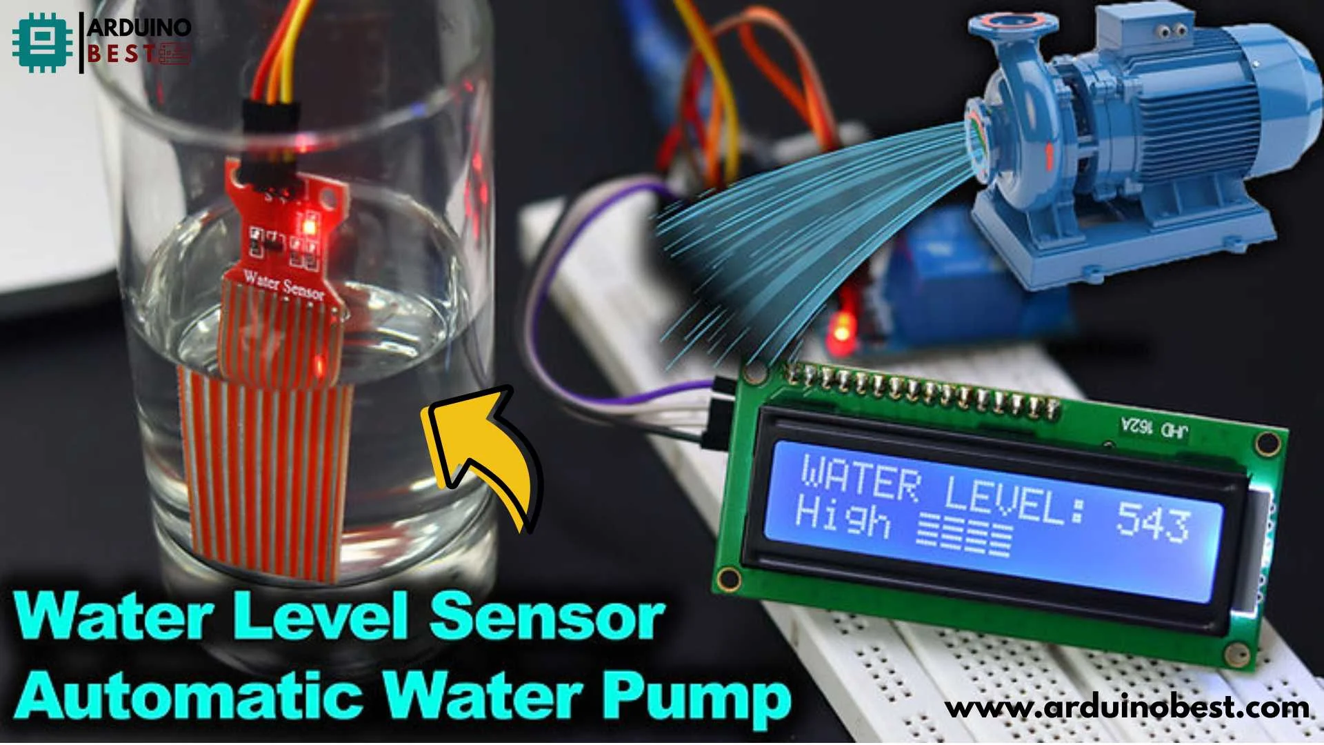
Water management is a critical concern in homes, farms, and industries. With rising water scarcity and the need for efficient resource management, technology has stepped in to offer innovative solutions. One such solution is the Arduino Water Level Indicator Automatic Water Pump System. This system integrates the power of Arduino technology to automate water pumping based on real-time water level data, ensuring that water is pumped only when necessary.
Overview of Water Management Challenges
Water conservation and efficient management have become vital in today’s world. The growing need for automated systems to handle water usage more intelligently is being addressed by technologies like Arduino-based solutions.
Role of Automation in Water Pumping Systems
Automation of water pumping systems offers numerous benefits. Automated systems can ensure water is pumped only when necessary, saving both energy and water, thus promoting sustainability.
Introduction to Arduino-Based Solutions
Arduino, an open-source electronics platform, is widely recognized for its versatility and cost-effectiveness. It offers a simple way to implement complex systems like water level monitoring and pump automation. With the help of Arduino boards, water level indicators and automatic pumps are now easier to control and manage.
To understand more about how automation is transforming industries, check out this relevant article on automation.
Understanding the Components
Building an Arduino Water Level Indicator Automatic Water Pump System requires a few essential components. Let’s dive into the main components and their functions.
Arduino Microcontroller
At the heart of this project lies the Arduino microcontroller. The most commonly used board is the Arduino Uno, which comes with sufficient I/O pins for a variety of sensors and modules. The microcontroller processes data from the sensors and triggers the pump to start or stop as required.
Water Level Sensors
Water level sensors are crucial for detecting the water levels. These sensors send signals to the Arduino board to determine whether the water has reached the desired threshold. Common sensor types include:
- Float switches: Simple, reliable sensors that detect water levels at specific points.
- Ultrasonic sensors: Provide a more accurate reading by measuring the distance between the sensor and water surface.
Relay Modules
A relay module allows the Arduino to control high-voltage devices like water pumps. The relay acts as a switch, enabling the Arduino to safely turn the pump on or off.
Water Pumps
The water pump is the actuator that moves water. There are different types of pumps used in such systems, such as submersible or centrifugal pumps. Depending on the system’s size and the water volume, you will select the appropriate pump.
LCD Displays
Incorporating an LCD display into the system allows users to monitor real-time data, including current water levels and system status. This makes troubleshooting and system management much easier.
System Design and Working Principle
The core idea behind this system is to create an automatic pump that responds based on the water level, which is sensed by the water level sensor. The following section provides an overview of how this system works.
System Overview
Here’s how the system works:
- The Arduino microcontroller reads data from the water level sensors.
- Based on the sensor readings, it activates or deactivates the water pump.
- The relay module ensures that the water pump receives the necessary electrical supply when needed.
- LCD displays show real-time feedback of the water level.
Note: For a better understanding of how automation is used in water management, you may find this guide to water-saving technologies quite useful.
Water Level Detection Mechanism
When water reaches a certain level, the water level sensor detects it and sends this data to the Arduino. The Arduino processes the input and decides whether to activate the pump. Sensors typically work by either detecting the presence or absence of water or by using ultrasonic signals to measure water levels.
Automatic Pump Activation and Deactivation
The water pump operates according to the data received from the sensor. When the water level drops below a threshold, the Arduino activates the pump. Similarly, when the water reaches the upper threshold, the system will turn off the pump.
Displaying Water Levels and System Status
The LCD display constantly updates users with the water levels and system status. For example, it can show the current water level, whether the pump is on or off, and any system errors.
Building the System
Required Components
To build the Arduino Water Level Indicator Automatic Water Pump System, you’ll need the following components:
- Arduino Uno board
- Water level sensors (float or ultrasonic)
- Relay module
- Water pump (suitable for your application)
- LCD display
- Wires and breadboard (for prototyping)
Circuit Diagram
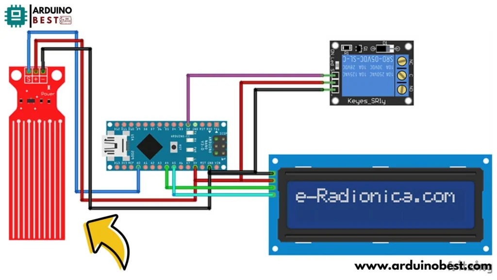
The circuit diagram shows how each component is connected to the Arduino. Here’s a simple diagram:

- Connect the water level sensor to the input pins of the Arduino.
- Connect the relay module to a digital pin on the Arduino.
- Wire the pump to the relay module.
- Connect the LCD display to the Arduino’s I2C pins for easy communication.
Assembly Instructions
Follow these steps to assemble the system:
- Set up the Arduino board on your workbench and connect it to the computer.
- Wire the water level sensor to the analog input pin on the Arduino.
- Connect the relay module to a digital output pin.
- Attach the pump to the relay module.
- Finally, connect the LCD display to the appropriate pins.
Arduino Code Explanation
Once your components are assembled, it’s time to write the code. The basic structure of the Arduino code involves:
- Initializing the pins for the water sensor, relay, and LCD.
- Reading the water level sensor and determining whether to activate the pump.
- Displaying relevant information on the LCD display.
#include <LiquidCrystal_I2C.h>
LiquidCrystal_I2C lcd(0x3F, 16, 2); // LCD HEX address 0x3F -- change according to yours

int val = 0;
int watersensor = A0;
int Motor = 2;
void setup() {
 Serial.begin(9600);
  lcd.begin();
  pinMode(Motor,OUTPUT);
  digitalWrite(Motor,LOW);
  // Print a message to the LCD.
  lcd.print("WATER LEVEL: ");
}

void loop() {
  val = analogRead(watersensor);
   Serial.println(val);
  lcd.setCursor(13,0);
  lcd.println(val);
  lcd.setCursor(0, 1);


  if (val<=100)
  {
    lcd.println("Empty ");
    digitalWrite(Motor,HIGH);
  }
  else if (val>100 && val<=450)
  {
    lcd.println("Low ");
    digitalWrite(Motor,HIGH);
  }
  else if (val>450 && val<=500)
  {
    lcd.println("Medium ");
  }
  else if (val>500)
  {
    lcd.println("High ");
    digitalWrite(Motor,LOW);
  }
  delay(1000);
}
Testing and Calibration
Initial Testing Procedures
Once everything is connected, it’s time to test the system. You can simulate water level changes by manually adjusting the water level in the tank. Check if the pump activates and deactivates as expected.
Calibrating Water Level Sensors
Water level sensors may need calibration to work optimally. This involves adjusting the threshold levels in the code and physically positioning the sensors at the correct water levels.
Troubleshooting Common Issues
- If the pump doesn’t turn on, check the relay module connections and the code logic.
- Ensure the water level sensor is correctly placed and calibrated.
- If the LCD shows incorrect data, verify the wiring and code for the display.
Advanced Features and Enhancements
Integrating Wireless Communication
To enhance the system, you can add wireless capabilities using Wi-Fi or Bluetooth modules, like the ESP8266 or HC-05, allowing you to monitor and control the system remotely.
Implementing Data Logging
By incorporating data logging, you can record and analyze the water levels over time. This could help you track the efficiency of the system and optimize water usage.
Adding Multiple Pump Control
For large installations, you can expand the system to manage multiple pumps by adding extra relay modules and controlling them individually with the Arduino.
Incorporating Alarms and Notifications
You can add alarms to alert users if the water level becomes too high or too low, preventing overflow or dry pump operation. This can be done via email or SMS notifications using modules like the SIM800L.
Applications and Use Cases
Residential Water Tank Management
In homes, an Arduino water level indicator and automatic pump system can ensure that water tanks are never overfilled or run dry, optimizing water usage.
Agricultural Irrigation Systems
In agriculture, the system can be used to control irrigation pumps based on soil moisture and water levels, ensuring optimal water use and reducing waste.
Industrial Fluid Level Monitoring
Industries dealing with large tanks or reservoirs can utilize this system to automate fluid management, reducing manual labor and improving safety.
FAQs
How accurate are the water level sensors?
The accuracy of the sensors depends on the type used. Float switches provide reliable binary signals, while ultrasonic sensors offer more precise measurements, but they may be affected by environmental conditions.
Can the system handle different types of water pumps?
Yes, this system can work with various types of pumps as long as the relay module is rated for the pump’s voltage and current.
Is it possible to integrate the system with existing home automation setups?
Yes, Arduino-based water level monitoring systems can be integrated into home automation systems such as Home Assistant or SmartThings, allowing for seamless control and monitoring.
What safety measures should be considered during installation?
Ensure that all electrical components are properly insulated and protected. Use fuses or circuit breakers to protect against electrical faults.
How can the system be expanded to monitor multiple tanks?
To monitor multiple tanks, you can replicate the system for each tank, using multiple Arduino boards and water level sensors, or employ a single Arduino with multiple sensor inputs.
Conclusion
Summary of Benefits
The Arduino Water Level Indicator Automatic Water Pump System provides a reliable, cost-effective solution for managing water usage in various applications. It saves energy, reduces water wastage, and offers real-time feedback.
Future Prospects
With advancements in IoT, wireless technology, and sensor accuracy, the future of water management systems is more connected and automated than ever before.
Here we suggest other Arduino Projects:
1- Complete Guide for DHT11/DHT22 Humidity and Temperature Sensor With Arduino
2- DHT11 – Temperature and Humidity Sensor
3- DHT22 – Temperature and Humidity Sensor (more accurate than DHT11)
4- BMP180 – Barometric Pressure and Altitude Sensor
5- BMP280 – Barometric Pressure & Temperature Sensor
6- BME280 – Temperature, Humidity, and Pressure Sensor
7- Arduino Flex Sensor Controlled Robot Hand
8- Arduino ECG Heart Rate Monitor AD8232 Demo
9- Arduino NRF24L01 Wireless Joystick Robot Car
10- Arduino Force Sensor Anti-Theft Alarm System
11- Arduino NRF24L01 Transceiver Controlled Relay Light
12- Arduino Rotary Encoder Controlled LEDs: A Complete Guide

