Table of Contents
Introduction
Building an Arduino OLED Stopwatch is a great way to learn about timekeeping, display modules, and button controls. Whether you want to create a simple stopwatch for a science project, sports timing, or just for fun, this project will teach you how to interface an OLED display with an Arduino microcontroller.
An OLED display is a fantastic choice because it offers high contrast, sharp text visibility, and low power consumption. In this tutorial, we will build a functional stopwatch using an Arduino board, a 0.96″ OLED screen, and push buttons to start, stop, and reset the timer. By the end of this guide, you will have a working stopwatch that accurately measures time in minutes, seconds, and milliseconds.
For more advanced Arduino display interfacing, check out this detailed OLED Display Guide. You can also learn more about handling push button debouncing here.
Understanding the Components
1. Arduino Microcontroller
- The Arduino UNO is the most commonly used board for beginners.
- Other options: Arduino Nano, Pro Mini, or Mega.
- The millis() function in Arduino helps track elapsed time without blocking the execution.
2. OLED Display
- We will use a 0.96″ I2C OLED display (SSD1306 driver).
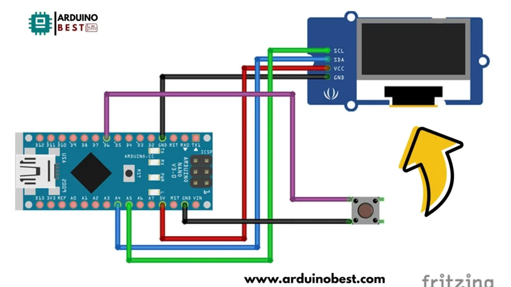
- It requires only four connections (VCC, GND, SDA, SCL), making wiring simple.
- Supports 128×64 pixel resolution, ideal for displaying numbers.
3. Push Buttons
- Three buttons will be used:
- Start: Begins the stopwatch.
- Stop/Pause: Freezes the time.
- Reset: Resets to zero.
- Uses internal pull-up resistors to simplify circuit design.
Required Materials
To build this project, you will need:
- Arduino Board (UNO, Nano, Pro Mini, or Mega)
- 0.96” OLED Display (SSD1306, I2C interface)
- Three push buttons (for start, stop, reset)
- Breadboard and jumper wires
- USB cable for programming the Arduino
Recommended sources for quality components:
Circuit Diagram and Assembly

1. Wiring the OLED Display
- VCC → 5V (or 3.3V depending on display version)
- GND → GND
- SDA → A4 (on Arduino UNO/Nano)
- SCL → A5 (on Arduino UNO/Nano)
2. Connecting the Push Buttons
- One side to GND, other side to digital pins (2, 3, 4)
- Enable internal pull-ups in code to avoid external resistors
3. Power Supply Considerations
- USB Power from PC
- Battery (Lithium-ion with a voltage regulator)
Programming the Arduino
1. Setting Up the Development Environment
- Install Arduino IDE.
- Download Adafruit SSD1306 & GFX libraries.
- Open Arduino IDE and create a new sketch.
2. Writing the Code
#include <SPI.h>
#include <Wire.h>
#include <Adafruit_GFX.h>
#include <Adafruit_SSD1306.h>
#include <Fonts/FreeSans9pt7b.h>
#include <Fonts/FreeSans18pt7b.h>
#include <Fonts/FreeSans12pt7b.h>

#define SCREEN_WIDTH 128 // OLED display width, in pixels
#define SCREEN_HEIGHT 64 // OLED display height, in pixels

// SCL A5
// SDA A4
#define OLED_RESET 0  // GPIO0
Adafruit_SSD1306 display(SCREEN_WIDTH, SCREEN_HEIGHT, &Wire, OLED_RESET);

#define LOGO_HEIGHT   16
#define LOGO_WIDTH    16


const unsigned char PROGMEM icon [] = {
0x00, 0x1F, 0xF8, 0x00, 0x00, 0x1F, 0xF8, 0x00, 0x00, 0x1F, 0xF8, 0x00, 0x00, 0x1F, 0xF8, 0x00,
0x00, 0x1F, 0xF8, 0x00, 0x00, 0x03, 0xC0, 0x00, 0x00, 0x00, 0x00, 0x40, 0x00, 0x00, 0x00, 0xE0,
0x00, 0x1F, 0xF8, 0xF0, 0x00, 0x7F, 0xFE, 0x70, 0x00, 0xFF, 0xFF, 0x20, 0x01, 0xF0, 0x0F, 0x80,
0x03, 0xC1, 0x83, 0xC0, 0x03, 0x81, 0x81, 0xC0, 0x07, 0x01, 0x80, 0xE0, 0x07, 0x01, 0x80, 0xE0,
0x0E, 0x01, 0x80, 0x70, 0x0E, 0x01, 0x80, 0x70, 0x0E, 0x03, 0xC0, 0x70, 0x0E, 0x03, 0xC0, 0x70,
0x0E, 0x03, 0xC0, 0x70, 0x0E, 0x01, 0x80, 0x70, 0x0E, 0x00, 0x00, 0x70, 0x07, 0x00, 0x00, 0xE0,
0x07, 0x00, 0x00, 0xE0, 0x07, 0x80, 0x01, 0xE0, 0x03, 0xC0, 0x03, 0xC0, 0x01, 0xE0, 0x07, 0x80,
0x00, 0xF8, 0x1F, 0x00, 0x00, 0x7F, 0xFE, 0x00, 0x00, 0x1F, 0xF8, 0x00, 0x00, 0x07, 0xE0, 0x00

};

const unsigned char PROGMEM swatch [] = {
0x03, 0xC0, 0x03, 0xC0, 0x03, 0xC0, 0x00, 0x08, 0x07, 0xEC, 0x0E, 0x70, 0x18, 0x18, 0x30, 0x0C,
0x30, 0x8C, 0x21, 0x84, 0x21, 0x84, 0x30, 0x0C, 0x10, 0x08, 0x18, 0x18, 0x0F, 0xF0, 0x03, 0xC0
};


void setup()   {
  pinMode(6,INPUT_PULLUP);  //Switch
  display.begin(SSD1306_SWITCHCAPVCC, 0x3C);  // initialize with the I2C addr 0x3C (for the 64x48)
  display.display();


  display.clearDisplay();
  display.setFont(&FreeSans9pt7b);
  display.drawPixel(10, 10, SSD1306_WHITE);
  display.setTextColor(WHITE);
  display.setCursor(0,0);
  display.print("Viral Science");
    display.display();
    delay(800);
}
int poz=1;
int broj=1;
int kretanjeY=30;

int sec1=0;
int min1=0;
unsigned long msec=0;
unsigned long mili=0;
int pres=0;
int fase=0;
int start=0;
unsigned long tim=0;
void loop()
  {
      display.clearDisplay();
      if(digitalRead(6)==0)
      {
        if(pres==0)
           {
            fase=fase+1;
            pres=1;
            if(fase>2)
            fase=0;
            }

        }else{pres=0;}

     if(fase==0)
      {
        display.setFont(&FreeSans12pt7b);
        display.setFont();
      display.setCursor(50,50);
      display.print("Start");
      display.drawBitmap(48, 8,  icon, 32, 32, WHITE);


      sec1=0;
      min1=0;
      tim=0;
      mili=0;
      msec=0;
      start=0;
      }

      if(fase==1)
      {
        display.clearDisplay();
        display.setFont(&FreeSans12pt7b);
        display.setFont();
        display.setCursor(37,0);
        display.print("Stopwatch");
        display.setFont(&FreeSans9pt7b);

        if(start==0)
          {
            start=1;
            tim=millis();
          }
       msec=(millis()-tim);


        min1=msec/60000;


        if((msec/1000)>59)
           {
            sec1=(msec/1000)-(min1*60);
            }else{
              sec1=msec/1000;
              }

          mili=(msec%1000)/10;

           display.setCursor(42,30);
           if(min1<=9)
           {
            display.print("0");
            display.print(min1);
            }else {display.print(min1);}

            display.print(":");

             if(sec1<=9)
           {
            display.print("0");
            display.print(sec1);
            }else {display.print(sec1);}
            display.setFont(&FreeSans12pt7b);
            display.setCursor(50,57);

                  if(mili<=9)
           {
            display.print("0");
            display.print(mili);
            }else {display.print(mili);}
       }

if(fase==2)
{
     display.clearDisplay();
     display.setFont(&FreeSans12pt7b);
        display.setFont();
        display.setCursor(52,0);
        display.print("Time:");
        display.setFont(&FreeSans9pt7b);
        display.setCursor(42,30);
           if(min1<=9)
           {
            display.print("0");
            display.print(min1);
            }else {display.print(min1);}

            display.print(":");

             if(sec1<=9)
           {
            display.print("0");
            display.print(sec1);
            }else {display.print(sec1);}
            display.setFont(&FreeSans12pt7b);
            display.setCursor(50,57);

                  if(mili<=9)
           {
            display.print("0");
            display.print(mili);
            }else {display.print(mili);}
             display.drawBitmap(105, 20,  swatch, 16, 16, 1);
             display.drawBitmap(12, 20,  swatch, 16, 16, 1);


  }


      display.display();
  }
Testing and Troubleshooting
- Ensure display is powered properly.
- Check push button wiring.
- Use
Serial.print()for debugging. - Confirm the correct OLED address (
0x3Cor0x3D).
Enhancements and Modifications
- Add Lap Functionality using an additional button.
- Improve Display Readability with different fonts.
- Save Lap Times to EEPROM for retrieval after power loss.
- Wireless Stopwatch using Bluetooth (control via mobile app).
Frequently Asked Questions
1. How can I modify the code to display hours?
Modify the displayTime() function to include hours:
int hours = (currentTime / 3600000) % 24;
display.printf("%02d:%02d:%02d", hours, minutes, seconds);
2. Why is my OLED display not working?
- Check power connections.
- Verify
0x3Cor0x3Daddress. - Try a different I2C port.
3. Can I use a different size OLED display?
Yes! Adjust the SCREEN_WIDTH and SCREEN_HEIGHT values.
Conclusion
This Arduino OLED Stopwatch Tutorial covered everything from hardware setup to coding. By following these steps, you now have a fully functional stopwatch with a precise timing mechanism. Experiment with modifications, such as adding a lap function or saving times to memory, to expand your project.
For further learning, explore advanced OLED display projects and other Arduino tutorials!
Here we suggest other Arduino Projects:
1- Complete Guide for DHT11/DHT22 Humidity and Temperature Sensor With Arduino
2- DHT11 – Temperature and Humidity Sensor
3- DHT22 – Temperature and Humidity Sensor (more accurate than DHT11)
4- BMP180 – Barometric Pressure and Altitude Sensor
5- BMP280 – Barometric Pressure & Temperature Sensor
6- BME280 – Temperature, Humidity, and Pressure Sensor
7- Arduino Flex Sensor Controlled Robot Hand
8- Arduino ECG Heart Rate Monitor AD8232 Demo
9- Arduino NRF24L01 Wireless Joystick Robot Car
10- Arduino Force Sensor Anti-Theft Alarm System
11- Arduino NRF24L01 Transceiver Controlled Relay Light
12- Arduino Rotary Encoder Controlled LEDs: A Complete Guide

