Table of Contents
Introduction
Monitoring heart rate and ECG (Electrocardiogram) signals is crucial for diagnosing and analyzing cardiac health. With the advancement of DIY electronics, building an ECG heart rate monitor using an Arduino and the AD8232 sensor has become an accessible and cost-effective solution.
The AD8232 ECG sensor module is a compact device that efficiently captures heart electrical signals. It provides a clear analog output that can be visualized using the Arduino Serial Plotter or other visualization tools. This tutorial walks you through setting up the Arduino ECG Heart Rate Monitor, understanding its components, and troubleshooting common issues.
For a deeper understanding of ECG technology and its medical applications, refer to MIT’s ECG Analysis Resources.
Understanding the AD8232 ECG Sensor
The AD8232 is a single-lead ECG module that:
- Measures the electrical activity of the heart
- Amplifies and filters weak ECG signals
- Outputs analog signals compatible with microcontrollers
Features of AD8232:
- Operates at 3.3V – 5V
- Low power consumption
- Lead-off detection for disconnected electrodes
- Compatible with Arduino, ESP32, and Raspberry Pi
For more details on how biosensors work in electronics, check out Texas Instruments’ guide on biosignal processing.
Components Required
To build an Arduino ECG Heart Rate Monitor, you need:
Hardware
- Arduino Board (Uno, Mega, or Nano)
- AD8232 ECG Sensor Module
- ECG Electrodes & Leads
- Breadboard and Jumper Wires
Software
- Arduino IDE (for programming)
- Processing IDE (for ECG visualization)
Wiring and Circuit Connections
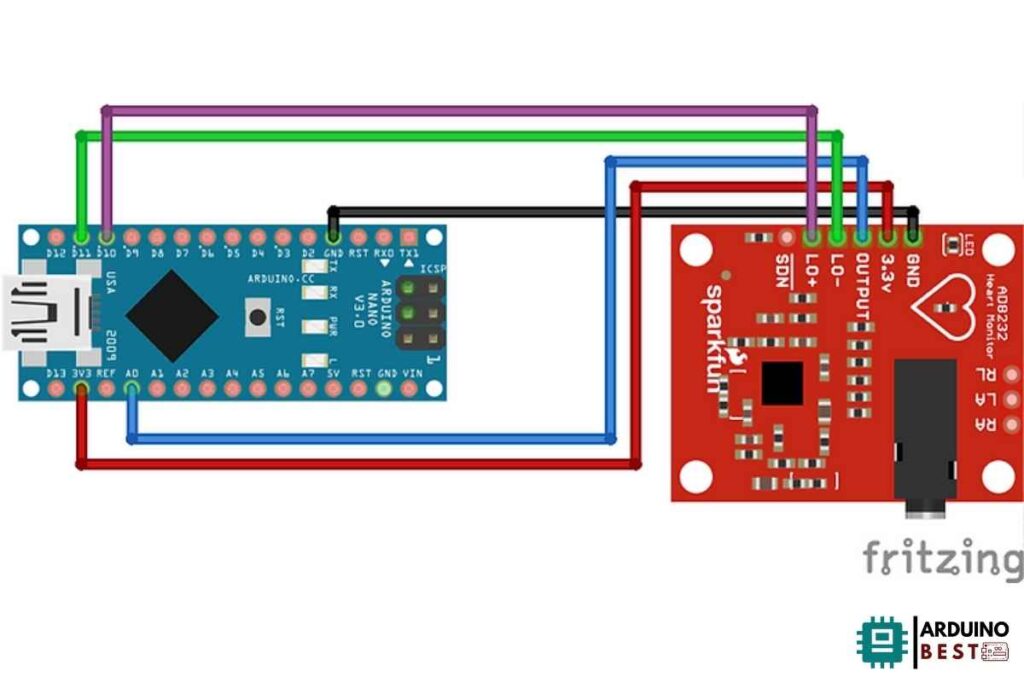
Connecting the AD8232 ECG sensor to an Arduino involves:
- Powering the Sensor:
- Connect VCC to 3.3V or 5V on Arduino
- Connect GND to GND on Arduino
- Signal Output:
- OUTPUT to A0 (Analog pin on Arduino)
- Lead-off Detection:
- LO+ and LO- for detecting lead disconnection
Ensure proper wiring to avoid signal loss. Here’s an illustrative wiring diagram for reference:

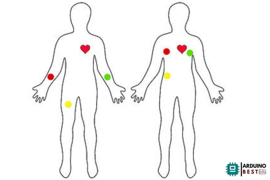
Placement of Electrodes
For accurate heart rate measurement, the electrodes should be placed correctly:
- RA (Right Arm) – Below the right collarbone
- LA (Left Arm) – Below the left collarbone
- RL (Right Leg, Ground) – Below the right ribcage

Ensure the skin is clean and dry before attaching electrodes to reduce noise interference.
Programming the Arduino
Use the following Arduino sketch to read ECG data from the AD8232 sensor:
void setup() {
  Serial.begin(9600);
  pinMode(A0, INPUT);
}

void loop() {
  int ecgValue = analogRead(A0);
  Serial.println(ecgValue);
  delay(1);
}
- Upload the code to the Arduino.
- Open the Serial Plotter (Tools > Serial Plotter) to visualize the ECG waveform.
Visualizing ECG Data
To enhance ECG data visualization, you can use Processing IDE:
void setup() {
// initialize the serial communication:
Serial.begin(9600);
pinMode(10, INPUT); // Setup for leads off detection LO +
pinMode(11, INPUT); // Setup for leads off detection LO -

}

void loop() {

if((digitalRead(10) == 1)||(digitalRead(11) == 1)){
Serial.println('!');
}
else{
// send the value of analog input 0:
Serial.println(analogRead(A0));
}
//Wait for a bit to keep serial data from saturating
delay(1);
}
This code plots real-time ECG signals, allowing better analysis.
Analyzing ECG Signals
Key ECG Waveforms
- P Wave: Represents atrial depolarization
- QRS Complex: Indicates ventricular depolarization
- T Wave: Represents ventricular repolarization
Heart Rate Calculation:
- Count the number of R-peaks in 60 seconds
- Convert it to BPM (beats per minute)
Troubleshooting Common Issues
No Signal or Flatline Readings
- Check wiring connections
- Ensure correct electrode placement
- Verify the power supply
Noisy or Erratic Signals
- Avoid movement during measurement
- Use electroconductive gel for better contact
- Reduce electrical interference by moving away from appliances
Advanced Applications
You can extend this project by:
- Adding Bluetooth Module (HC-05) for wireless ECG streaming
- Integrating IoT (ESP8266/ESP32) to send data to cloud platforms
- Using AI/ML for arrhythmia detection
Safety Considerations
- The AD8232 ECG module is not for medical diagnosis
- Always consult a medical professional for accurate heart monitoring
- Avoid using it for prolonged continuous monitoring
FAQs
1. Can the AD8232 sensor be used with other microcontrollers?
Yes, it works with ESP32, Raspberry Pi, and STM32.
2. How accurate is the AD8232 ECG sensor?
It provides decent accuracy for educational and hobbyist purposes but is not a medical-grade device.
3. Why is my ECG signal noisy?
- Poor electrode contact
- Movement during recording
- Electrical interference from nearby devices
4. Is it safe to use the AD8232 on humans?
Yes, but follow safety precautions and do not use it as a replacement for clinical ECG devices.
Conclusion
Building an Arduino ECG Heart Rate Monitor with the AD8232 sensor is a great DIY electronics project. By following proper setup and troubleshooting steps, you can successfully measure and visualize ECG signals. Consider advancing your project with IoT connectivity or machine learning analysis for deeper insights.
For more guidance on Arduino-based projects, explore Adafruit’s tutorial on bio-sensors.
Here we suggest other projects Arduino:
1- Complete Guide for DHT11/DHT22 Humidity and Temperature Sensor With Arduino
2- DHT11 – Temperature and Humidity Sensor
3- DHT22 – Temperature and Humidity Sensor (more accurate than DHT11)
4- BMP180 – Barometric Pressure and Altitude Sensor
5- BMP280 – Barometric Pressure & Temperature Sensor

