Introduction
The world of robotics is evolving rapidly, with innovations that bring human-like motion to mechanical structures. One of the most exciting DIY projects in this field is building an Arduino Flex Sensor Controlled Robot Hand. This project integrates flex sensors, servo motors, and an Arduino board to mimic human hand movements.
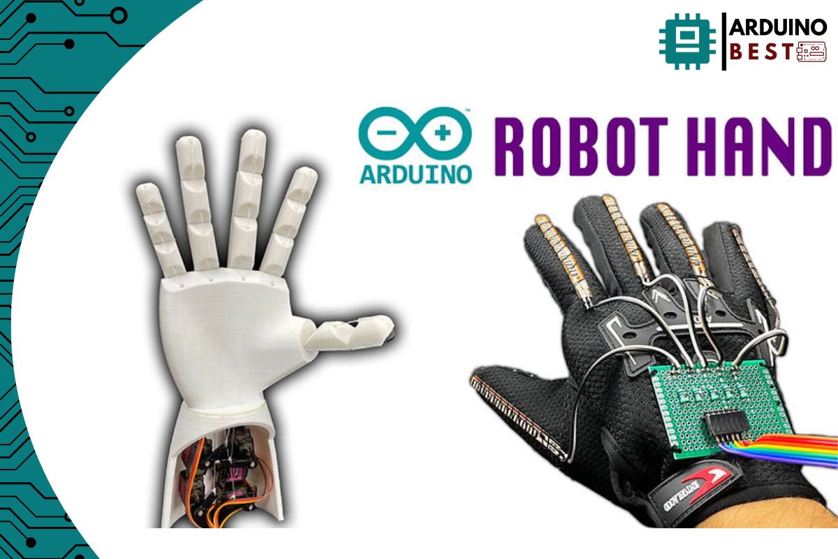
By using flex sensors attached to a glove, the movement of each finger can be captured and translated into corresponding movements in a robotic hand. This concept has vast applications in prosthetics, teleoperation, and assistive technology. If you’re interested in exploring Arduino’s potential, check out this comprehensive guide to Arduino to get started.
Understanding Flex Sensors
Flex sensors are resistive devices that change their resistance when bent. This property makes them ideal for measuring finger movement in robotic hands. There are two main types:
- Conductive ink-based flex sensors – More accurate and widely used.
- Fiber-optic flex sensors – Less common but highly sensitive.
To understand how flex sensors work in detail, refer to this technical breakdown of flex sensors.
Components Required
To build an Arduino-controlled robotic hand, you will need:
Hardware Components:
- Arduino Uno (or any compatible board)
- Flex sensors (5 pieces, one for each finger)
- Servo motors (5 pieces to control finger movement)
- 10kΩ resistors (for voltage divider circuits)
- Glove (to attach sensors)
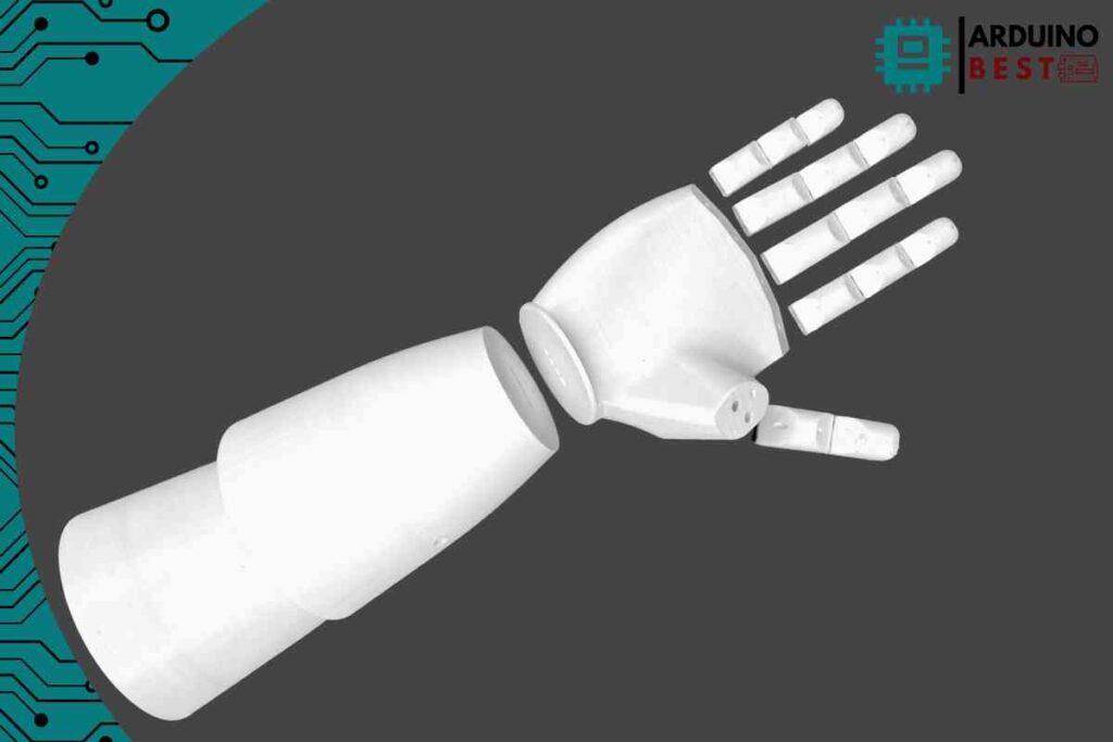
- 3D-printed hand parts (or alternative materials)
- Breadboard and jumper wires
- Power supply (battery or USB-powered)
Software Requirements:
- Arduino IDE
- Servo control libraries
Building the Flex Sensor Glove
To ensure accurate motion tracking, follow these steps:
- Attach each flex sensor to the corresponding finger of the glove using tape or fabric glue.
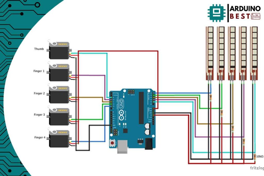
- Solder wires to the flex sensors and connect them to the Arduino via voltage divider circuits.
- Use heat shrink tubing or electrical tape to secure connections.
Constructing the Robotic Hand
For an efficient robotic hand, consider:
- Using 3D printing for precision and durability.
- Attaching servo motors to each finger joint.
- Connecting fingers to servos using nylon strings to replicate tendon movement.

Circuit Design and Wiring
- Connect flex sensors to analog input pins on the Arduino.
- Use voltage dividers to stabilize sensor readings.
- Wire each servo motor to PWM pins on the Arduino.
- Ensure a stable power source to prevent voltage fluctuations.

Programming the Arduino
- Read flex sensor values using
analogRead(). - Map values to servo motor positions using
map(). - Smooth out sensor inputs to prevent jitter.
- Upload and test using this sample code:
//Idle  790--835--793--859--827--
//Close 880--844--802--866--831--

#include <Servo.h>

Servo servo1;
Servo servo2;
Servo servo3;
Servo servo4;
Servo servo5;

int flex1 = A1;
int flex2 = A2;
int flex3 = A3;
int flex4 = A4;
int flex5 = A5;
;
void setup()
{
  Serial.begin(9600);
  servo1.attach(2);
  servo2.attach(3);
  servo3.attach(4);
  servo4.attach(5);
  servo5.attach(6);
}


void loop()
{
  int flex1_pos;
  int servo1_pos;
  flex1_pos = analogRead(flex1);
  servo1_pos = map(flex1_pos, 840, 900, 180, 0);
  servo1_pos = constrain(servo1_pos, 180, 0);
  servo1.write(servo1_pos);

  int flex2_pos;
  int servo2_pos;
  flex2_pos = analogRead(flex2);
  servo2_pos = map(flex2_pos, 879, 882, 0, 180);
  servo2_pos = constrain(servo2_pos, 0, 180);
  servo2.write(servo2_pos);


  int flex3_pos;
  int servo3_pos;
  flex3_pos = analogRead(flex3);
  servo3_pos = map(flex3_pos, 828, 824, 180, 0);
  servo3_pos = constrain(servo3_pos, 180, 0);
  servo3.write(servo3_pos);

  int flex4_pos;
  int servo4_pos;
  flex4_pos = analogRead(flex4);
  servo4_pos = map(flex4_pos, 874, 878, 0, 180);
  servo4_pos = constrain(servo4_pos, 0, 180);
  servo4.write(servo4_pos);

  int flex5_pos;
  int servo5_pos;
  flex5_pos = analogRead(flex5);
  servo5_pos = map(flex5_pos, 855, 851, 180, 0);
  servo5_pos = constrain(servo5_pos, 180, 0);
  servo5.write(servo5_pos);


  /*
Serial.print(servo1_pos);
Serial.print("--");
Serial.print(servo2_pos);
Serial.print("--");
Serial.print(servo3_pos);
Serial.print("--");
Serial.print(servo4_pos);
Serial.print("--");
Serial.print(servo5_pos);
Serial.println("--");
*/

Serial.print(flex1_pos);
Serial.print("--");
Serial.print(flex2_pos);
Serial.print("--");
Serial.print(flex3_pos);
Serial.print("--");
Serial.print(flex4_pos);
Serial.print("--");
Serial.print(flex5_pos);
Serial.println("--");

  delay(300);


}
Calibration and Testing
- Calibrate sensor values by adjusting minimum and maximum flex readings.
- Test each finger to ensure the robotic hand moves smoothly.
- Troubleshoot common issues like incorrect servo alignment or unstable readings.
Wireless Control Options
For an advanced version, integrate:
- nRF24L01 modules for wireless communication.
- A second Arduino as a receiver.
- Enhanced programming logic for real-time wireless control.
For more information, visit this wireless communication tutorial.
Applications and Future Enhancements
The Arduino Flex Sensor Controlled Robot Hand can be used in:
- Prosthetics for amputees.
- Remote-controlled robotics for hazardous environments.
- Sign language interpretation.
Future improvements could include:
- Haptic feedback to enhance sensory perception.
- AI-based gesture recognition for more intuitive control.
- Stronger materials for durability and efficiency.
FAQs
How does a flex sensor work in a robotic hand?
Flex sensors detect bending movements, translating resistance changes into electrical signals that drive servo motors.
Can I build this without prior Arduino experience?
Yes! By following structured guides, even beginners can complete this project.
How can I improve the accuracy of flex sensor readings?
Use high-quality sensors, proper calibration, and filtering algorithms.
Can I control the robotic hand wirelessly?
Yes, using nRF24L01 or Bluetooth modules to transmit flex sensor data remotely.
Conclusion
Building an Arduino Flex Sensor Controlled Robot Hand is an exciting project that bridges electronics, mechanical engineering, and programming. Whether for assistive devices or teleoperation, this DIY robotic hand opens doors to endless possibilities. Get started today and explore the future of robotics!
Here we suggest other projects:
1- Complete Guide for DHT11/DHT22 Humidity and Temperature Sensor With Arduino
2- DHT11 – Temperature and Humidity Sensor
3- DHT22 – Temperature and Humidity Sensor (more accurate than DHT11)
4- BMP180 – Barometric Pressure and Altitude Sensor
5- BMP280 – Barometric Pressure & Temperature Sensor6- BME280 – Temperature, Humidity, and Pressure Sensor

