
Table of Contents
Introduction
The 8×8 dot matrix display module with MAX7219 driver IC is a fundamental component in many electronics projects today. It enables the creation of visually dynamic outputs such as scrolling text, animated symbols, and simple games with minimal wiring complexity. Thanks to the MAX7219 driver IC, controlling a matrix of 64 LEDs becomes incredibly simple and efficient.
This module finds its use in a variety of applications including DIY projects, signage displays, and learning platforms for understanding SPI communication and LED matrix driving. Whether you are a hobbyist or a professional developer, mastering the 8×8 dot matrix module opens the door to many creative possibilities.
Understanding the 8×8 Dot Matrix Display
An 8×8 LED matrix consists of 64 LEDs arranged in 8 rows and 8 columns. These LEDs are wired in a specific way that allows them to be controlled individually without needing 64 separate pins.
- Common cathode and common anode configurations are the two standard wiring types.
- Each LED can be addressed using row and column scanning techniques.
- Common applications include scrolling text banners, digital clocks, and simple animations.
If you want to dive deeper into module specifics, you can explore the MAX7219 8×8 LED Matrix Module Overview.
Overview of the MAX7219 Driver IC
The MAX7219 driver IC is specifically designed to simplify the process of controlling an LED matrix. Instead of individually managing 64 LEDs, you send data serially through a simple SPI-compatible interface.
Key features of the MAX7219 include:
- Built-in BCD decoder
- Multiplex scan circuitry
- Segment and digit drivers
- 8×8 static RAM for display data storage
- Ability to daisy-chain multiple modules
To see the complete datasheet for the chip, visit the MAX7219 Datasheet.
Moreover, because the driver handles current control internally, you can connect your LED matrix display without additional resistors, making the design cleaner and more reliable.
Pin Configuration and Wiring
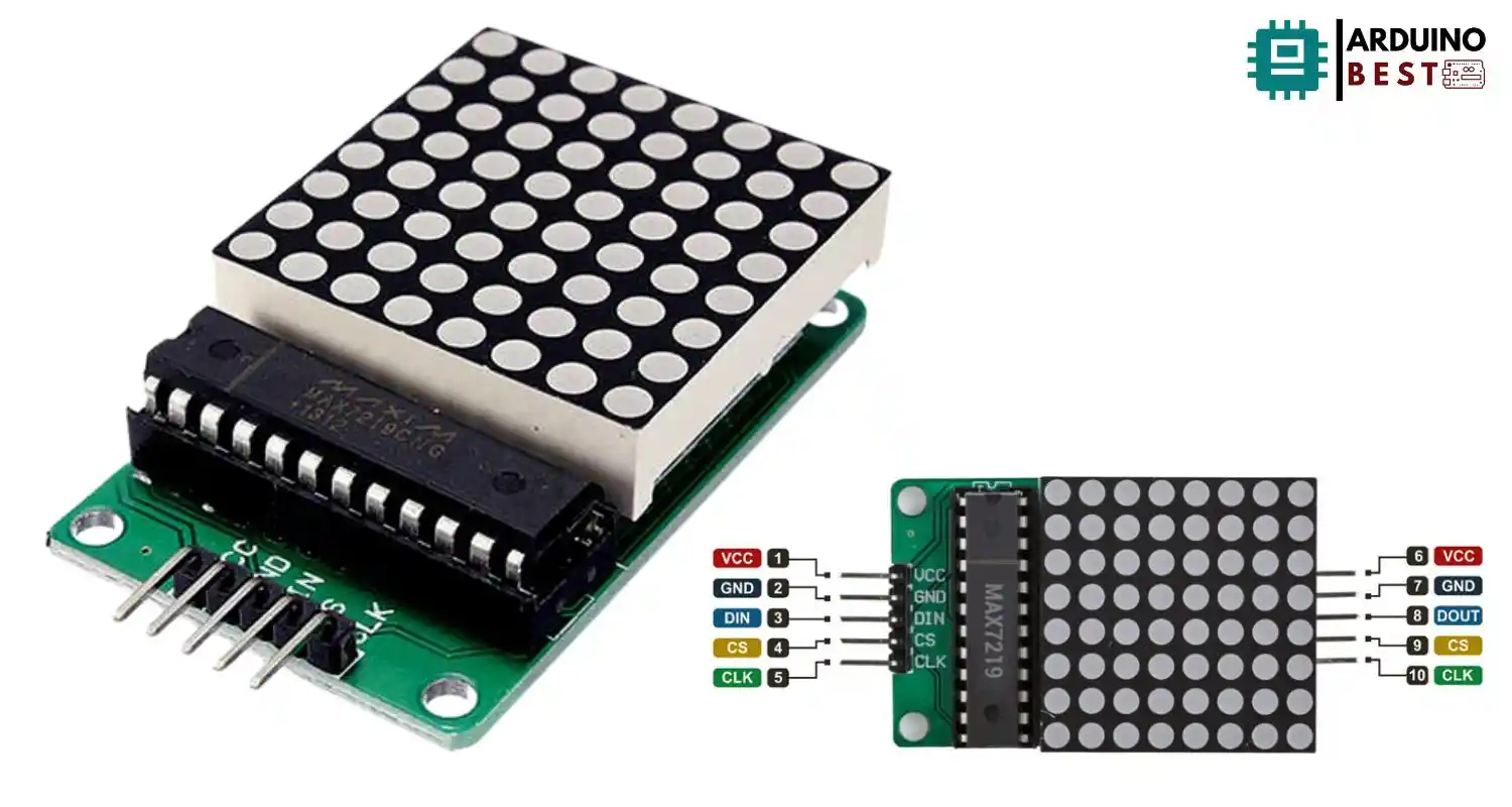
When using an 8×8 matrix with MAX7219, it is critical to understand the pin layout:
- VCC: Connects to the 5V supply.
- GND: Ground connection.
- DIN: Data input from the microcontroller.
- CLK: Clock signal.
- CS (or LOAD): Chip select to enable data input.
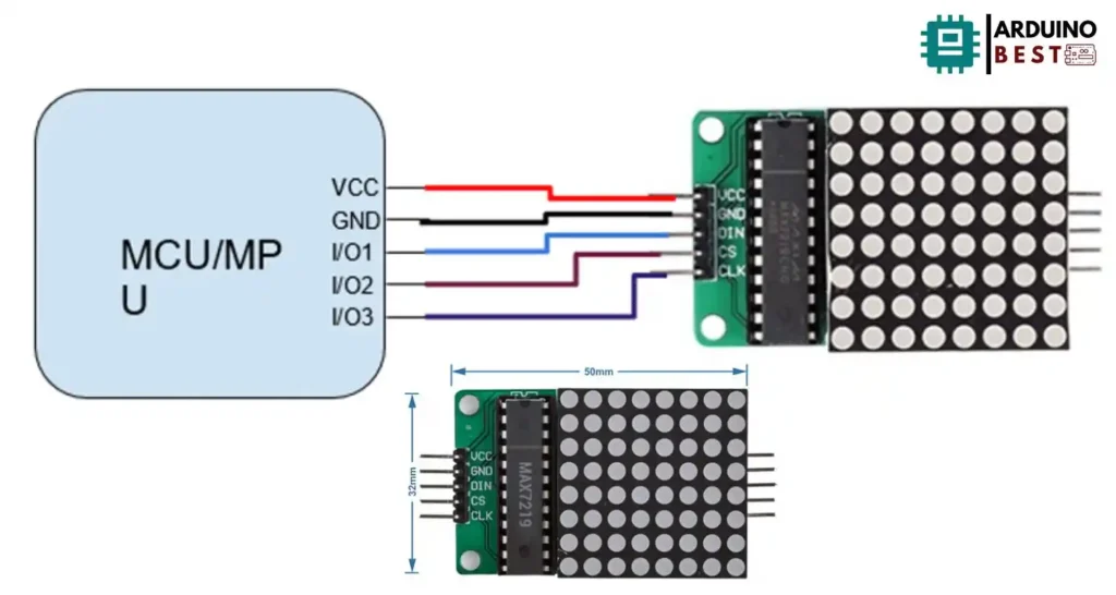
Proper wiring ensures reliable communication. For example:
- Connect DIN to your microcontroller’s SPI MOSI pin.
- CLK connects to the SPI clock pin.
- CS connects to any free digital pin configured as the SPI chip select.
Always ensure correct orientation and careful wiring to avoid damaging the components.
Setting Up with Arduino
To set up the 8×8 dot matrix module with an Arduino, you will need:
- Arduino Uno or any compatible board
- MAX7219 module
- Jumper wires
Steps to follow:
- Install libraries like LedControl or MD_MAX72XX from the Arduino IDE Library Manager.
- Connect the module using SPI wiring.
- Use basic code to light up the display.
Sample code snippet:
#include <LedControl.h>

LedControl lc = LedControl(12, 11, 10, 1);

void setup() {
  lc.shutdown(0, false);
  lc.setIntensity(0, 8);
  lc.clearDisplay(0);
  lc.setLed(0, 3, 3, true);
}

void loop() {
}
You can adjust brightness with the setIntensity() method and update patterns dynamically.
Advanced Projects and Applications
Once you have the basic setup working, you can move into more exciting projects using the 8×8 dot matrix module:
- Scrolling text displays: Display custom messages that scroll across multiple modules.
- Simple games: Create classics like Pong or Snake.
- Sensor integration: Make the display interactive by linking it to motion sensors or temperature sensors.
- Daisy-chaining: Link multiple MAX7219 modules together for larger displays.
Tutorials like Scrolling Text with MAX7219 offer detailed project examples and inspiration.
Troubleshooting Common Issues
When working with the 8×8 LED matrix, a few problems might arise:
- Unresponsive module: Check wiring and confirm VCC and GND are connected properly.
- Mirrored or inverted display: Verify the software library settings for orientation.
- Flickering LEDs: Ensure a stable 5V power supply, and consider using capacitors.
- Dim display: Adjust brightness settings in your code with
setIntensity().
Careful setup and verification help avoid most issues.
Best Practices for Optimal Performance
For best results with your 8×8 dot matrix display:
- Use a high-quality 5V regulated power supply.
- Limit current draw by managing brightness appropriately.
- Allow for heat dissipation by not overdriving the LEDs.
- Shield long signal lines to prevent electromagnetic interference.
- Regularly update libraries and firmware for bug fixes and new features.
Applying these practices ensures your project remains reliable over time.
FAQs
How do I connect multiple 8×8 matrices together?
Use the DOUT pin of the first module and connect it to the DIN pin of the next module. Power and clock lines can be shared among all modules.
Can I use the MAX7219 with microcontrollers other than Arduino?
Yes, the MAX7219 is compatible with microcontrollers like ESP32, Raspberry Pi, and STM32, provided they support SPI communication.
How do I control brightness levels?
Brightness is controlled via a command to the driver IC using the setIntensity() function in libraries like LedControl.
What is the maximum number of modules I can connect?
While technically up to 8 modules are manageable via SPI, practical limits depend on your microcontroller’s memory and power capabilities.
Why is my display showing garbled characters?
Garbled output usually results from loose connections, incorrect wiring, or mismatched software settings.
Conclusion
The 8×8 dot matrix display module with MAX7219 driver IC offers a simple and powerful way to bring dynamic visual effects into your electronics projects. With minimal wiring and easy programming, it is accessible even to beginners. By following best practices and exploring creative projects, you can fully leverage the potential of these versatile modules for both fun and functional applications.